LED and Light Circuit
LED Solar Lantern Lights
Published:2013/9/2 21:01:00 Author:lynne | Keyword: LED Solar Lantern Lights | From:SeekIC

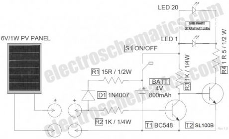
Circuit of the LED solar lantern lights presented here is built around one 6V/1W Solar Panel (PhotoVoltaic Panel) and a 4V/800mAh Lead-Acid Battery. Here, commonly available 5mm White Straw Hat LEDs are used as the light source.
DC 6V supply from the solar panel is fed to the rechargeable battery through diode D1 (1N4007) and resistor R1 (15R). Diode D1 functions as a reverse current protector and resistor R1 limits the battery charging current to a safe value. Transistor T1 (BC548) is here wired as an automatic switch to control the LED driver transistor T2 (SL100). T1 disables T2 when the circuit receives sufficient power output from the solar panel.
Switch S1 is an ordinary power on/off switch. Finally, resistor R4 determines the operating current of the white LED (LED 1 – LED 20) assembly. No-load voltage of the solar panel is near 7.2Volt. When connected with the circuit, the PV panel gives around 170mA of current at 6VDC output in middling sunlight, which is more than enough for this circuit. When fully charged, no-load output voltage of the 4V lead-acid battery is near 4.6Volt. According to datasheet, Forward Voltage of the 5mm (actually 4.8mm) White Straw Hat LED (used here) is 3 to 3.2volt, and maximum Continuous Current is about 20mA (Peak Current 30mA).
Reprinted Url Of This Article:
http://www.seekic.com/circuit_diagram/LED_and_Light_Circuit/LED_Solar_Lantern_Lights.html
Print this Page | Comments | Reading(3)

Article Categories
power supply circuit
Amplifier Circuit
Basic Circuit
LED and Light Circuit
Sensor Circuit
Signal Processing
Electrical Equipment Circuit
Control Circuit
Remote Control Circuit
A/D-D/A Converter Circuit
Audio Circuit
Measuring and Test Circuit
Communication Circuit
Computer-Related Circuit
555 Circuit
Automotive Circuit
Repairing Circuit
Code: