Control Circuit
0.3 Second to 10 Hours Timer Relay with 4541 IC
Published:2013/8/28 1:27:00 Author:lynne | Keyword: 0.3 Second to 10 Hours Timer Relay with 4541 IC | From:SeekIC

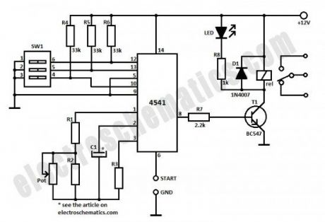
This timer relay circuit uses the CD4541 IC and has 2 timing variations configurable with RC elements. The specifications of this timer are:
modes of operation: astable/monostable
the output has a 6A/250V relay with NC/NO contacts
LED signals exiting the timing state
manual programming done with a DIP-switch
12V voltage operation
For the 0.3 second to 10 minutes timer version the potentiometer is 100kΩ, R1 = 9.1kΩ, R2 = 910kΩ, R3 = 220kkΩ and C1 = 100µF.
For the 15 seconds to 10 hours timer version the potentiometer is 1MΩ, R1 = 51kΩ, R2 = 1.2MΩ, R3 = 1.2MΩ and C1 = 1µF.
The operating mode is selected with the third contact of SW1:
ON position = monostable
O position = astable
In order to start the timining you have 2 possibilities: you either connect the START point to ground GND and in this case the timer starts when you connect it to the voltage supply or you can place a switch to start it.
All the resistors are 0.25W and C1 must have a good stability over time.
Reprinted Url Of This Article:
http://www.seekic.com/circuit_diagram/Control_Circuit/03_Second_to_10_Hours_Timer_Relay_with_4541_IC.html
Print this Page | Comments | Reading(3)

Article Categories
power supply circuit
Amplifier Circuit
Basic Circuit
LED and Light Circuit
Sensor Circuit
Signal Processing
Electrical Equipment Circuit
Control Circuit
Remote Control Circuit
A/D-D/A Converter Circuit
Audio Circuit
Measuring and Test Circuit
Communication Circuit
Computer-Related Circuit
555 Circuit
Automotive Circuit
Repairing Circuit
Code: