
Circuit Diagram
Index 376
20 kbit optical cable receiving circuit
Published:2011/12/1 20:30:00 Author:May | Keyword: 20 kbit optical cable, receiving
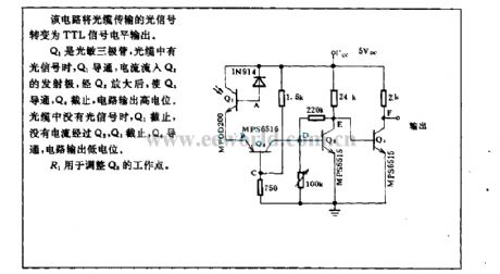
This circuit turns theoptical signal transmitted by optical cable to TTL signal level output.
Q1 is photistor. When the optical cable receives signal, Q1 is breakover, the current flows into emitter of Q2. After being enlarged by Q2, the current makes Q3 breakove and Q4 close, the circuit outputs high level. When the optical cable can not receive signal, Q1 is closed. There is no current flowing into Q2, and Q3 is closed, Q4 is breakover, and the circuit output is in low level.
R1 is used for adjusting the operation point of Q3. (View)
View full Circuit Diagram | Comments | Reading(1196)
200W automatic voltage adjustment type AC stabilized voltage supply circuit diagram
Published:2011/12/1 20:32:00 Author:May | Keyword: 200W, automatic voltage adjustment, AC, stabilized voltage supply

View full Circuit Diagram | Comments | Reading(1627)
20V regulated power supply circuit
Published:2011/12/2 0:19:00 Author:May | Keyword: 20V, regulated power supply

The maximum wasted power of compensating pipe T1 shown in diagram (a) is 5.6W. The radiator of compensating pipe T1 can be made by aluminium plate with 2mm thick and 100mm×100mm area. Need regulated voltage can be adjusted to 20V by 1kΩ regulation resistor which is connected at base of transistor T3.
transformer winding number: n1=1600turns, 0.25mm copper lacquered wire n2=180turns, 0.7mm copper lacquered wire
The maximum wasted power of compensating pipe T1a and T2b shown in diagram (b) can reach 14.5W. Each transistor radiator can be made by aluminium plate with 2mm thich and 120mm×120mm area.
transformer winding number: n1=1190turns, 0.35mm copper lacquered wire n2=145turns, 0.8mm copper lacquered wire
(View)
View full Circuit Diagram | Comments | Reading(1527)
100W VMOS pipe inverted power supply circuit
Published:2011/12/1 20:45:00 Author:May | Keyword: 100W, VMOS pipe, inverted power supply


The circuit of this system is simple and easy to debugging. The performance of this system is reliable. This system can automatically converting, inverting and charging. It also has jar battery indicator. Thanksfor adopting high power VMOS pipe, its efficiency is high and its cost is lower. This system is fit for electrophile assembling and installing.
The circuit working principle is shown in diagram 1. Multivibrator consists of VT1 and VT2. Its oscillator frequency is 5Hz. When voltage decreases, in order to get the same frequency, the power supply of oscillator is regulated by voltage regulator tube VD1. The square-wave voltage isoutput by multivibrator, then it directly pushes VMOS high power pipe. The 220V AC isset up by transformer and extract from socket CZ.
(View)
View full Circuit Diagram | Comments | Reading(1160)
10000 h timing circuit with minutes and seconds
Published:2011/12/1 20:56:00 Author:May | Keyword: 10000 h, timing, minutes and seconds
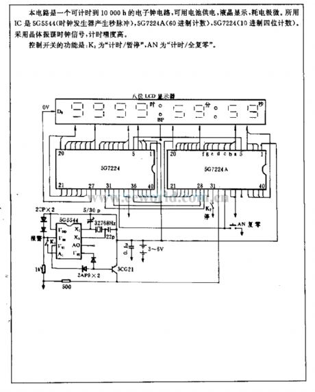
This circuit is electronic clock circuit. It can time to 10000h. It is supplied bybattery for liquid crystal display. Its power consumption is very small. The used IC is 5G5544 (clock generator generates pulse per second) , 5G7224A (60 system counting) , 5G7224 ( 10 system four digit counting) . The circuit uses crystal oscillation clock signal. Its time precision is high.
The function of control switch is: K2 is time/ suspend , AN is time/ all zero reset .
(View)
View full Circuit Diagram | Comments | Reading(1275)
100W sunset control circuit
Published:2011/12/1 21:02:00 Author:May | Keyword: 100W, sunset control
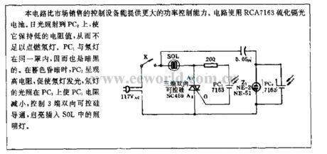
Comparing to controller equipment in the market, this circuit has larger control ability. The circuit adopts RCA7163cadmium sulfide photocell. The sunlight shines on PC2. It canmake it stay on low resistance. So it is not enough to light up the neon light. PC1 and neon light are in the same shade, so it is dark. When darkness is colsed, PC2 is in high resistance topromote neon lightand light up it. The light of neon light shines on PC1. The PC1's resistance is decreased. It can control three ends ofbidirectional thyristor to turn on. Then the lamp inserted in S0L is lit. (View)
View full Circuit Diagram | Comments | Reading(613)
65W fluorescent light using 24V chopper
Published:2011/12/1 21:09:00 Author:May | Keyword: 65W fluorescent light, 24V chopper

This circuit is self-oscillation push pull chopper circuit. It is supplied from 24V battery. Its frequency is 4kHz. Its major advantages are: 1. It does not require choke, and it only uses 0.12μF small-capacity capacitor to limit lighting tube current to belower than 630mA; 2. chopper transformer is much smaller than low frequency period; 3. when it isin high frequency, the efficiency is high.
Main technical data of the circuit:working volt: 24V working band: 4kHzcurrent sinking: 4.5Aconsumed power: 108Wlamp power: 65Wefficiency: 60%
Transformer data:n1=n2=10turns, 1.0mm copper lacquered wiren3=n4=2 turns, 0.75mm copper lacquered wiren5=120turns, 0.75mm copper lacquered wire (View)
View full Circuit Diagram | Comments | Reading(1999)
DZW75-48/5050II high frequency converting circuit
Published:2011/12/4 20:29:00 Author:May | Keyword: high frequency converting
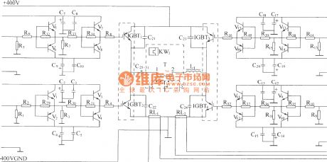
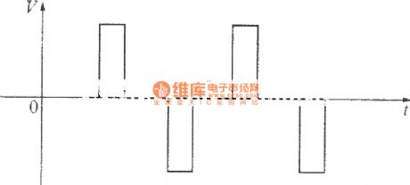
High frequency converter adopts full bridge structure. IGBT in four arms are separately driven by four drivers which are mutual isolated. Their working power supply is 300V. Under the effect of drive pulse, high frequency switching tubes on the two crosses are turned on at the same time, or cut off at the same time, thereby getting high frequency pulse voltage at main transformer’s first and second coils, in order to achieve high frequency conversion of DC/AC. When both 1# and 4# drive pulses are in positive potential, IGBT1, IGBT4 are turned on at the same time, at this time, both the drive pulse of IGBT2 and IGBT3 are in negative potential, cut off reliably, the first coil of main transformer T will have current, the current direction is from 1 end to 2 end, and the primary induced voltage is set to positive pulse, and its width is about 300V. (View)
View full Circuit Diagram | Comments | Reading(740)
DZW75-48/5050II steady voltage and current limiting, current sharing circuit
Published:2011/12/4 20:22:00 Author:May | Keyword: steady voltage, current limiting, current sharing
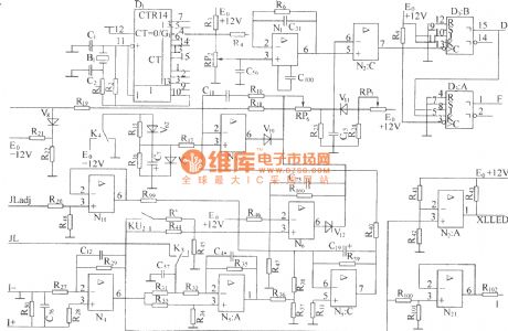
The steady of output voltage is mainly using the principle of negative feedback, the sample value of output value is returned back to error comparator, and it uses error voltage output by error comparator to control or modulate (adjust) the output pulse width of pulse width modulator, thereby adjust the height of output voltage to achieve the purpose of steady voltage output. As shown in the diagram, sampling voltage LOAD (-) is sent to “-” end of error comparator N3 resistor R19, then the “+” end of N3 is connected to -4.3V reference voltage offered by -12V power supply and voltage regulator diode V9 by resistor R17, when it is in normal operation, K4 contact point lies to -12V. In fact, N3 is a different amplifier.
(View)
View full Circuit Diagram | Comments | Reading(832)
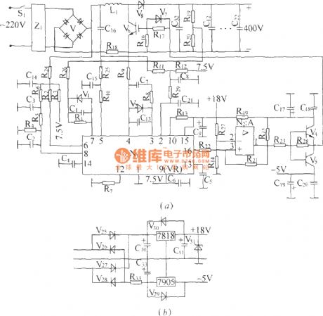
DZW75-48/5050II input circuit
Published:2011/4/14 6:11:00 Author:may | Keyword: input
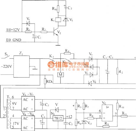
(1) 220V (5Hz) alternating voltagepass Z1 circuit filter filtering, then it will send to the connect point of AC over voltage, under voltage protect relay K2. When normal working, K2 connect point should up-close, connect AC 220V voltage to AC current-limiting resistance R4 (after starting up, delay period of time, R1 is short-circuit by K1 connect point), send to power frequency bridge rectifier rectifying, get DC 300V output voltage through parallel connection condenser bank smoothed filtering, finish power frequency AC/DV transform. R2 is leak resistance.
(2) Z1 circuit filter is used for suppressing and absorbing obstruction of strong pulse to rectifier on electric network, increasing the reliability of rectifier. At the same time, the good common mode and difference module insertion loss of circuit filter can effectively inhibit inverted output high frequency interfering signal generated by high frequency switching converter,it canisolate rectifier and electric fence, avoid mutual interference.
(3) AC over voltage, under voltage protection circuit, AC 220V voltage sended to reducing transformer after through circuit filter filtering.
(4)AC current limiting delay circuit, AC voltage can switch-in machine in normal work range, build time at auxiliary power supply after AC power supply switch-in, andby a period of time delay after auxiliary power supply build, it can make AC current-limiting resistance short-circuit, this period time is AC current limiting delay, it is finish by AC current limiting delay circuit. (View)
View full Circuit Diagram | Comments | Reading(1537)
Introduction of high frequency winding coiling
Published:2011/11/23 2:27:00 Author:May | Keyword: high frequency winding, coiling
Introduction of high frequency winding coiling (switching power supply 12W transformer dual group with feedback group)
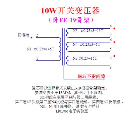
10W switching power transformer
Magnetic core can choose horizontal type installing EE-19 and determined by skeleton.
Installing height is less than 15mm. Other sizes have no limit.
N1 primary coil is row winding at bottom level and is isolated from second level.
Second level N3, secondary level, third level, N4 levelare isolated with fourth level. Fourth level N2 isin feedback level.
N3, N4are using three wires to winding together. (View)
View full Circuit Diagram | Comments | Reading(1403)
The production circuit diagram of Performance reliable high power switching power supply
Published:2011/11/21 21:49:00 Author:May | Keyword: Performance reliable, high power, switching power supply

This circuit is a simple and reliable high power switching power supply. Theproduct is designed by a factory. It is applied in large light. Some explanation of this transformer is in the following:
(EI-50L) is storage power inductor. It adopts EE-50 magnetic core or EI-50 magnetic core. EI-50 magnetic core is output transformer. You can produce according to the explanation in the circuit diagram. EG6 is magnetic ring with 12mm diameter. The coiling is also made according to the explanation in the circuit diagram.
No-load running test is less than 20mA. The transfer efficiency is more than 90%. The maximum power is 800W. ( when 60V/13.5A, the input AC is 3.1A) (View)
View full Circuit Diagram | Comments | Reading(3831)
The special chip driving high-fidelity and pure sine wave inverter 1 based on Class D amplifier
Published:2011/11/10 2:18:00 Author:May | Keyword: Class D amplifier, special chip, sine wave inverter
View full Circuit Diagram | Comments | Reading(6772)
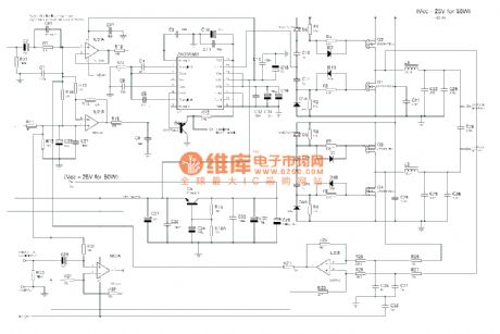
TL494 control car audio inverter power supply
Published:2011/11/10 2:16:00 Author:May | Keyword: control, car audio inverter, power supply

TL494 controls car's audio inverter power supply: it is high-fidelity audio power supply of custom car.It can work reliably without adjusting according this circuit diagram set. (View)
View full Circuit Diagram | Comments | Reading(15538)
Stabilized voltage inverter 12V-220V 200W
Published:2011/11/22 1:37:00 Author:May | Keyword: Stabilized, voltage inverter, 12V-220V 200W

Stabilized voltage inverter 12V-220V 200W is shown in the following diagram. It can adopt existing dual 12V-200W mains transformer. But its invert efficiency is low.
(View)
View full Circuit Diagram | Comments | Reading(8463)
The simplest practical switching power supply (one triode)
Published:2011/11/22 1:37:00 Author:May | Keyword: simplest practical, switching power supply, one triode

It can make the frequency bein the range of 30kHz-45kHzby adjusting C3 and R5. Output voltage needs to be regulated voltage. Output current can reach 500mA. Effective power is 8W. Efficiency is 87%. This circuit can worknormally with non requirement about others. (View)
View full Circuit Diagram | Comments | Reading(2255)
DZW75-48/50(50II) type power factor compensation
Published:2011/12/5 1:13:00 Author:May | Keyword: power factor compensation
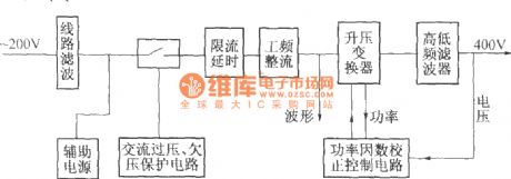
The elementary diagram of DZW75-48/5050II power factor compensation:
DZW75-48/5050II power factor compensation circuit:
In the diagram, (a) is compensation circuit, (b) is auxiliary power supply. It mainly consists of N1, power factor calibration control module and some support circuits. The internal part of N1 consists of saw-tooth wave generator, pulse width modulator and multiple comparator circuit and so on. The frequency of saw-tooth wave generator is determined by out-connected capacitor and resistor. This machine make the frequency of its output pulse work at 50 kHz, and the width of output pulse is determined by the error voltage after a general comparison treatment. It has three sampling and comparison circuits. In fact, V6 is integrated chip consisting VMOS tube, promotion diode and rectifier bridge.
(View)
View full Circuit Diagram | Comments | Reading(709)
DZW75-48/50(50II) high frequency rectifying filtering circuit
Published:2011/11/23 1:27:00 Author:May | Keyword: high frequency rectifying, filtering
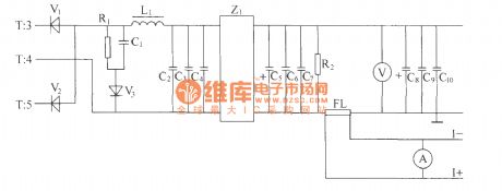
Positive and negative alternation pulse voltage of high frequency transformer T’s secondary induction pass full wave rectifier composed of high frequency switching diodes V1, V2, then pass L power line filter composed of L1 inductor and capacitor C2, C3, C4 and Z 1 :power supply filter and other smoothing filters,then the output end gets 48V DC voltage output with high and low frequency noise to meet the index demand. The pulse width isdirectly decided bythe output voltage. When the pulse width is wide, the output voltage will be high; if the pulse width is narrow, output voltage islow. In order to measureanddisplay output DC voltage, we can parallel connect a voltmeter in output end. R2 is the leak resistor. FL is thecurrent divider. The voltage value in the justify of FL also can be uses as output current sampling signal and itcan besent to stabilize voltage and limit current. R1, C1 and V3 make up the RCD absorber circuit to absorb overshoot voltage of secondary. (View)
View full Circuit Diagram | Comments | Reading(611)
Delay circuit with operational amplifier
Published:2011/8/29 1:51:00 Author:Jessie | Keyword: Delay circuit , operational amplifier
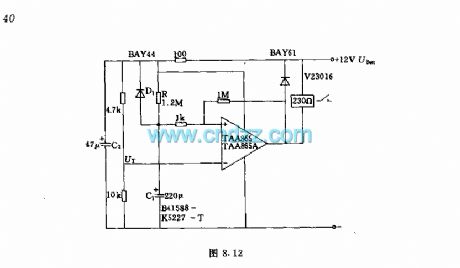
After plug-in power, the relay on the output terminal closes immediately, and release safter the prescribed delay time.Technical characteristicsWorking voltage: 12V + 20%Delay time: about 260sRepeat preparation time: about 12s
(View)
View full Circuit Diagram | Comments | Reading(2905)
Phase control circuit of Bi-directional thyristor without hysteresis
Published:2011/8/29 0:59:00 Author:Jessie | Keyword: Phase control , Bi-directional thyristor , without hysteresis
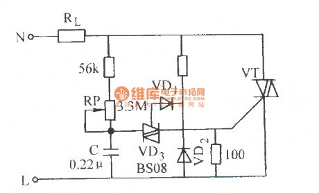
View full Circuit Diagram | Comments | Reading(1064)
| Pages:376/2234 At 20361362363364365366367368369370371372373374375376377378379380Under 20 |
Circuit Categories
power supply circuit
Amplifier Circuit
Basic Circuit
LED and Light Circuit
Sensor Circuit
Signal Processing
Electrical Equipment Circuit
Control Circuit
Remote Control Circuit
A/D-D/A Converter Circuit
Audio Circuit
Measuring and Test Circuit
Communication Circuit
Computer-Related Circuit
555 Circuit
Automotive Circuit
Repairing Circuit