
Circuit Diagram
Index 379
Bi-directional thyristor gate pole limiting resistor adjustment circuit
Published:2011/8/28 21:20:00 Author:Jessie | Keyword: Bi-directional thyristor, gate pole , limiting resistor

View full Circuit Diagram | Comments | Reading(730)
Zero type recitfying and stabilizing voltage circuit
Published:2011/11/23 2:06:00 Author:May | Keyword: Zero type, recitfying, stabilizing voltage
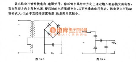
In this circuit, it connects to thecapacitor and resistor components in front of voltage regulator tube. Voltage regulator tube connectsto AC power supply by input capacitor in the direction of breaking over, but it limits current in the direction of breaking. It can make the followed capacitor recharge. Thereby it can make the output voltage be stable. Voltage pulse of this circuit is larger than bridge type circuit. Because it is directly connected with AC power supply, its consumption current is small. (View)
View full Circuit Diagram | Comments | Reading(641)
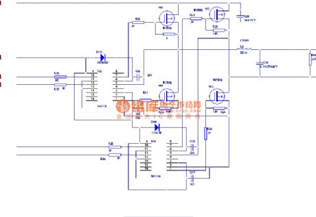
Control circuit composed of six inverter and push pull circuit
Published:2011/11/23 2:25:00 Author:May | Keyword: Control, six inverter, push pull

Here we adopt push pull circuit supply by 8V constant voltage in order to make SIPMOS transistor (it is not shown in the diagram) have the requiredraising speed when it is turned on. Push pull circuit transistor is controlled by six inverters in parallel connection. It adops optocoupler conponents in order to isolate with the level of input circuit. (View)
View full Circuit Diagram | Comments | Reading(1036)
Seedling raising shed humidity and temperature monitor circuit
Published:2011/11/23 2:23:00 Author:May | Keyword: Seedling raising shed, humidity and temperature monitor

When growing seeding in seeding raising shed, the main thing is to grasp thehumidity and temperature of hot bed soil. Seeding raising shed humidity, temperature monitor introduced in this example can send out voice, light alarm signal when the soil in hot bed is too dry or too wet or the temperature in shed is too high, too low. It can remind the farmer to treat this situation in time.
This seedling raising shed humidity, temperature monitor circuit consists of soil humidity monitor circuit, temperature monitor circuit and voice alarm circuit. The circuit is shown in the diagram.
Theselection of components and parts
R1~R6 adopts 1/4W metal film resistor or carbon film resistor
RT1 and RT2 all adopt negative temperature factor thermal resistor (the resistance in normal temperature is about 3kΩ)
RP1~RP4 all adopt organic solid potentiometer
C adopts ceramic dielectric capacitor or glass glaze condenser
VL1~VIA all adopt φ3mm high brightness LEDs; VL1 and VL3are green, VL2 and VIAare red
V1 adopts S9012 or 3CG21 type silicon PNP transistors; V2 adopts S9011 or 3DG6 type NPN transistor; V3 adopts S8550 or 3CG8550 type silicon PNP transistor
IC adopts CD4069 or CC4069, MC14069 type six not gate IC
BL adopts 0.25W, 812 dynamic loudspeaker
GB uses low capacity non-maintaining storage battery or four AA battery
S adopts small type single-pole tumble switch
The two poles of temperature detection probe make up to adopt graphite carbon piece in D size dry battery (using insulating board to set, the distance between two poles is 4cm, wire lead weld on the copper cap of graphite carbon piece). (View)
View full Circuit Diagram | Comments | Reading(1375)
Reference voltage source using BJT
Published:2011/11/23 2:21:00 Author:May | Keyword: Reference voltage source using BJT

This circuit adopts voltage regulator tube D1, transistor T and resistor R1, R2 to make up constant-current source. It can supply for parallel circuit composed of reference diode D2 and load resistor RL (here is 68kΩ). Its current is about 7.6mA. Because the current on D1 is much higher than base-emitter current of transistor and the current on D1 is designed to be very high (5mA), the change of emitter current and reference diode current caused by the dispersion of transistor data and input current is very small.
(View)
View full Circuit Diagram | Comments | Reading(2188)
Constant current source using operational amplifier TAA861
Published:2011/12/5 0:54:00 Author:May | Keyword: Constant current source, operational amplifier

The output current of this circuit is determined by the following formula:IA=(Uref β)/R β+1 AIn the formula: Uref is reference voltage generated by voltage regulator tube, β is magnification coefficient of power tube. If β is big enough, IA≈Uref/R AThe technical data of this circuit:input voltage: UE=10~20Voutput current: IA=100mAlargest output current (R=805Ω): IAmax≈750mAcurrent adjustable rate (when △UE=1V, UE=15V, IA=100mA): F= △IA/IA=2×10-4load adjustable rate (when Ua=0~10V, UE=15V, IA=100mA): F=△IA/IA=1.6×10-3output current temperature factor: α<5×10⁻⁴V/K (View)
View full Circuit Diagram | Comments | Reading(1881)
Bi-directional thyristor control inductive load circuit
Published:2011/8/28 21:18:00 Author:Jessie | Keyword: Bi-directional thyristor, control inductive load

View full Circuit Diagram | Comments | Reading(1243)
Bi-directional thyristor AC voltage adjustment circuit
Published:2011/8/28 21:17:00 Author:Jessie | Keyword: Bi-directional thyristor, AC, voltage adjustment

This circuit uses bi-directional thyristor to control heater load RL. Trigger circuituses a single junction transistor oscillator. It's supplied by AC power, resistor R1 and regulator tube V2. Single junction transistor output is sent to bi-directional thyristor circuit by bi-directional thyristor. If you want to control the speed of DC motor M, you can connect the two-way thyristor to the motor in series according to the dotted line in the figure. Parallel resistor is mainly used to absorb the possible over-voltage on the TRIAC caused by inductive load discharging. (View)
View full Circuit Diagram | Comments | Reading(1292)
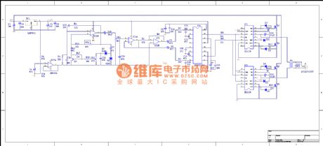
The special chip driving high-fidelity and pure sine wave inverter based on Class D amplifier
Published:2011/11/10 2:18:00 Author:May | Keyword: Class D amplifier, specialchip sine wave inverter
View full Circuit Diagram | Comments | Reading(6742)
Fishing device 1
Published:2011/11/22 1:45:00 Author:May | Keyword: Fishing device

View full Circuit Diagram | Comments | Reading(1990)
Fishing Device
Published:2011/11/22 1:38:00 Author:May | Keyword: Fishing Device
View full Circuit Diagram | Comments | Reading(2212)
DC voltage converter with output voltage U>100V and phase power Po=25W
Published:2011/12/5 1:17:00 Author:May | Keyword: DC voltage converter, output voltage U>100V, phase power Po=25W
This circuit works by the principle of blocking converter. That is, it can send energy to load in the period when transistor is cutting off. Divider circuit R1, R2 and C2are used for guarantee the circuit can start reliable oscillation when input voltage Ui≥2V. The circuits can non-load operate in a short time. But it does not have the function of protection when output end is short.
The main technical data of this circuit:
Output power: Po=2.5W;
Output voltage: Uo≥100V;
Oscillation frequency: f≈20kHz;
Efficiency: η=0.76.
Transistor data:
n1=50turns, 0.33 copper enamel wire;
n2=13turns, 0.1mm copper enamel wire;
n3=50turns, 0.3mm copper enamel wire. (View)
View full Circuit Diagram | Comments | Reading(548)
一1.5V-120V/10MV DC voltage converter
Published:2011/12/5 1:15:00 Author:May | Keyword: 一1.5V-120V/10MV, DC, voltage converter
It best adopts single end blocking converter to change 1.5V voltage into 120V voltage. The reason is that the voltage changing at this time is higher than transformer's. Its working process: transformer stores energy in the period when the transistor is breaking over, but it will send the energy to load in the period when it is cutting off.
Main technical data:
Working voltage: 1.5V;
Working current: 16mA;
Output voltage: 120V;
Load resistance: 1MΩ;
Frequency: 5kHz.
Transformer data:
n1=100turns, 0.12mm copper enamel wire;
n2=50turns, 0.05mm copper enamel wire;
n3=1000turns, 0.05 copper enamel wire. (View)
View full Circuit Diagram | Comments | Reading(1384)
30W micro switch regulated power supply composed of TOP224Y
Published:2011/12/5 1:25:00 Author:May | Keyword: 30W, micro switch, regulated power supply

Here we introduce a kind of 30W micro switch regulated power supply composed of TOP224Y, its circuit is shown in the diagram. Its feature is using TL431 to replace regulation tube VDz2 in the sampling circuit. That is, it can reach the technical target of micro switch power supply by using high stability band gap reference voltage Uref to replace normal zener diode. The excellent characteristic is concentrated reflecting on, when AC input voltage u changes from 85V to 265V, Sv=±0.2%; when load current changes from 10% (0.2A) to 100% (2A), S1=±0.2%. It can compare with linearity integrated power supply.
Electric isolation outside error amplifier consists of TIA31(IC3) and optical coupler NEC2501(IC2). When it is conncted with internal error amplifier, it can greatly improve regulation performance by precision adjusting the control end of TOP224Y(IC1). It can get sampling voltage after +15V regulation output dividing by R4 and R5. Compared with TL431's internal 2.5V reference voltage, it can adjust control end current Ic by changing potential of K end to control LED's current. R4 and C8 also can determine the frequency property of outside error amplifier.
(View)
View full Circuit Diagram | Comments | Reading(6928)
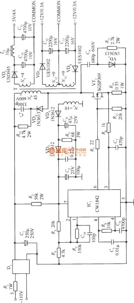
The single-ended reflection converter circuit composed of CW1842 and external connected MOS power transistor
Published:2011/11/22 1:36:00 Author:May | Keyword: single-ended, reflection converter , external connected, MOS power transistor
View full Circuit Diagram | Comments | Reading(718)
Forward conversion type switching stabilized voltage supply isolating by photocoupler
Published:2011/11/22 1:28:00 Author:May | Keyword: Forward conversion, switching, stabilized voltage supply, photocoupler

The diagram shows forward conversion switching stabilized voltage supply isolated by photo-coupler. VT1 is switching tube; VT2 and the photistor of photo-coupler VT3 make up compound variable resistance tube; VT4 and VT5 make up compound error amplifier. N2 is the secondary winding of high transformer T for DC outputting and sampling. N3 is self-oscillation positive feedback coil. In this circuit, DC voltage output end connects with sampling circuit of error amplifier, but thesignal output by amplifier is not connecting to the circuit, thereby it achieves the electrical isolation of sampling circuit for error amplifier and switching tube.
When output voltage increases, emitter current of compound error amplifier VT4 and VT5 increases. This current passes the LED in photo-coupler to make its illumination become larger. (View)
View full Circuit Diagram | Comments | Reading(966)
The resonant converter schematic diagram based on step-down circuit (series)
Published:2011/11/22 1:09:00 Author:May | Keyword: resonant converter , step-down circuit
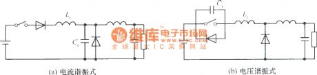
In the generalused switching stabilized voltage supply, it can use theresonantswitch to replace the step-down convertor's shape, and that is the resonant converter circuit. The diagram shows the example of changing step-down convertor to resonant converter: diagram (a) is current resonant ; diagram (b) is voltage resonant.
(View)
View full Circuit Diagram | Comments | Reading(1407)
Matsushita L12H power supply
Published:2011/11/22 1:04:00 Author:May | Keyword: Matsushita, power supply

TV using Matsushita L12H power supply includes: Matsushita TC-230H, TC-2030DHN, TC-830D, TC-840D, etc.
Oscillation circuit
One way of the 300V DC voltage on the C836 is added to the internal switch's C pole of IC801 pin 1 by the P1, P2 windings of T801, then it is added to the B pole of the IC801's pin 2 internal tube by the R803, then the switch tube begins to turn on, E polar current is out from IC801's pin (4). T801's P1, P1 winding current increases to generate induced voltage and couple to the F2, F3 windings, then F2, F3's induced voltage polarity is that the F3 is negative and F2 is positive, the voltage is added to the IC801 (2 ), ( 4 ) feet through C806, R804, so that the switch current is further increased, and the strong positive feedback make the switch be quickly saturated . (View)
View full Circuit Diagram | Comments | Reading(1196)
U9D6121G一001(TV and video)infrared remote control launch circuit
Published:2011/8/29 2:09:00 Author:Jessie | Keyword: infrared, remote control
μPD6121G is infrared remote control launch circuit, which is suitable for TV and video, etc. The Internal circuit is composedof the oscillating circuit, points frequency device, clock produces circuit, keyboard input circuit, keyboard output circuit, control circuit, data registers, etc.
Technical characteristicsCMOS large scale integrated circuits.Power supply voltage, the range is 2.0~3.3V.Power consumption is small. When it is static, the current is less than 1μA.Supporting use with model CXK20106A.
20-pin dual in-line plastic package.
(View)
View full Circuit Diagram | Comments | Reading(2649)
LG Elevator band-type brake circuit
Published:2011/8/26 3:49:00 Author:Jessie | Keyword: Elevator, band-type brake

View full Circuit Diagram | Comments | Reading(816)
| Pages:379/2234 At 20361362363364365366367368369370371372373374375376377378379380Under 20 |
Circuit Categories
power supply circuit
Amplifier Circuit
Basic Circuit
LED and Light Circuit
Sensor Circuit
Signal Processing
Electrical Equipment Circuit
Control Circuit
Remote Control Circuit
A/D-D/A Converter Circuit
Audio Circuit
Measuring and Test Circuit
Communication Circuit
Computer-Related Circuit
555 Circuit
Automotive Circuit
Repairing Circuit