
Circuit Diagram
Index 375
Agricultural application pesticide light control black light lamp circuit
Published:2011/8/10 3:58:00 Author:Nicole | Keyword: Agricultural application pesticide, light control, black light lamp
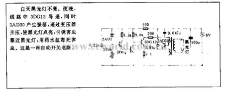
During the day, the black light lampdoes not light. At night, 3DG12 turns on, at the same time, 3AD30 produces oscillation, it is rised by transformer, then the black light lamp is lightened, it can attract pests, then it will use drug tank to poison the pests. It is an automatic switch circuit. (View)
View full Circuit Diagram | Comments | Reading(908)
Image interface circuit
Published:2011/8/10 3:58:00 Author:Nicole | Keyword: image
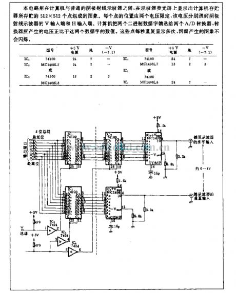
This circuit is used between computer and ordinary cathode ray oscillograph, the oscillograph phosphor screen displays an image composed of 512*512 dots, the image is stored in computer memory. The position of each dot is limited by two voltages, those voltages are transported to the V input terminal and H input terminal of cathode ray oscillograph. Two binary data words is fed to two A/D converter by computer, the voltage produced by converter is proportional to the value of these data words. These dots repeated display many times per second, so the produced image will not flash. (View)
View full Circuit Diagram | Comments | Reading(646)
Up/down slope control circuit
Published:2011/8/10 4:05:00 Author:Nicole | Keyword: up slope, down slope, control circuit
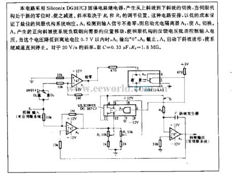
This circuit adopts Siliconix DG387CJ solid circuit relay to produce cut-over from up slope slope to down slope, when servo mechanism is in new zero, the circuit will slow down. The slope factor depends on the adjusting position of R1, R2. This circuit arrangement can ensure the best servo mechanism system response with low cost. The input singal detected by A1 is not zero, then starting the photoelectric isolator A3, to cut over A4. The system load is moved to the needed position by positive slope which is produced by A5, then the feedback voltage of servo mechanism will counteract the control input voltage. When this voltage drops to within 0.7V from ground potential, A1 outputs 0 , A3 cuts off. A4 starts down slope waveform, the system will slow down and until stop. For 20V/s slope factor, it takes C=0.33μF, R3=1.8MΩ. (View)
View full Circuit Diagram | Comments | Reading(1235)
Sound control, dimming commercial colored lamp control circuit
Published:2011/8/10 4:04:00 Author:Nicole | Keyword: sound control, dimming, color lamp
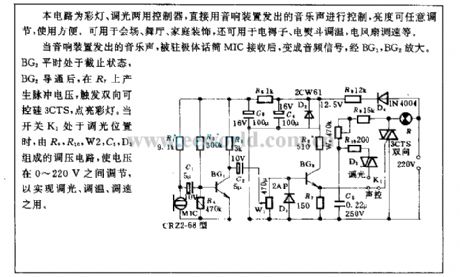
This circuit is colored lamp, dimming double-duty controller. It is direct conreolled by the musical sound of audio device, the brightness can be discretionarily adjusted, and it is convenient for using. It can be used in meeting place, dance hall, home decoration, and it also can be used in electric mattress, electric iron temperature adjustment, electric fan speed regulation and so on.
When the audio device sends out musical sound, after being received by electret microphone MIC, it will be changed into audio singal, it is amplified by BG1, BG2. BG2 is in off condition in normal times, after BG2 turning on, R7 will produce pulse voltage to trigger TRIAC 3CTS, and light up the color lamp. When switch K1 is in dimming position, the voltage is adjusted between 0~220V by the voltage regulation circuit which is composed of R9, R10, W2, C5, D3, to achieve dimming, temperature adjustment, speed regulation. (View)
View full Circuit Diagram | Comments | Reading(887)
An example of LM317T application circuit
Published:2011/8/10 4:03:00 Author:Nicole | Keyword: application circuit
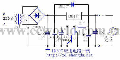
The load of this adjustable regulated power supply which is produced by LM317T is always damaged due to the output voltage rises which is caused by potentiometer's poor contact. If adding a triode(as shown in the figure) under normal circumstances, T1's base level is 0, T1 turns off, it has no influence on circuit; when the W1 is poor contact, T1's base current rises, when it rises to 0.7V, T1 turns on, it makes the regulation terminal voltage of LM317T drop, the output voltage drops too, then to protect the load. If it removes the triode, and cuts W1 connection conter point, 3.8V bulb is burned down immediately, the output voltage reaches 21V. When it is added T1, the brightness of bulb reduces, then the LM317T output voltage is only 2V, it can effectively protect load.
(View)
View full Circuit Diagram | Comments | Reading(2663)
Unfired bricks moisture detector 3
Published:2011/8/10 4:12:00 Author:Nicole | Keyword: Unfired brick, moisture detector
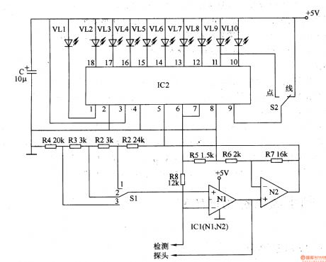
This unfired bricks moisture detector circuit is composed of detection input circuit and LED display circuit, it is shown in the figure 8-77.
The detection input circuit iscomposed of detector probe, operation amplifier integrated cirucit IC1(N1, N2), resistors R1-R8 and water content measurement area selection switch S1.
LED display circuit consists of LED linear analogue display drive integrated circuit IC2, LED VL1-VL10 and point/line display selection switch S2.
S1 has three shifts, 1 shift tests 13% water content area, 2 shift tests 14% water content area, 3 shift tests 15% water content area.
(View)
View full Circuit Diagram | Comments | Reading(1357)
Motor protector 6
Published:2011/8/10 4:11:00 Author:Nicole | Keyword: Motor protector
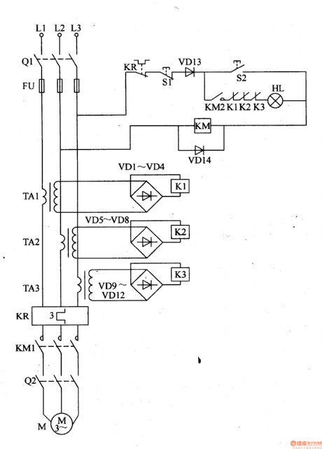
This motor protector circuit is composed of current transformer TA1-TA3, heat relay KP, rectifier diodes VDl-VDl4, relays K1-K3, starter button S1, stop button S2 and AC contactor KM, it is shown in the figure 8-42.
For some reasons, phase power is cut off, then this current transformer losses the work current, relay releases, the normally open contact is cut off, AC contactor KM cuts off and releases, then the motor M's work power is cut off, it can protect motor from damaging.
(View)
View full Circuit Diagram | Comments | Reading(717)
VCT3802 CPU, VCD single chip small-signal process integrated circuit diagram
Published:2011/8/10 4:11:00 Author:Nicole | Keyword: single chip, small-signal process


VCT3802 is a new type CPU, VCD single chip small-signal process integrated circuit which is used in multi-system color TV, it is widely used in new type large-screen color TV.
1, functions and features
The main functions of VCT3802 integrated circuit including: microprocessor, TV/AV switching circuit, brightness signal process circuit, color singal demodulator circuit, RGB matrix circuit, RGB singal selection switch circuit, adjusting-free line/field oscillation circuit and line/field pulse singal forming circuit, pincushion distort correcting signal process circuit and imaging state regulating circuit. The typical application circuit of this integrated block is shown in the figure 1-1.
The figure 1-1 is the typical application circuit of VCT3802 integrated block
2, pin function and data
The pin function and data of VCT3802 integrated circuit is shown in the table 1-2
The table 1-2 is the pin function and data of VCT3802 integrated circuit (View)
View full Circuit Diagram | Comments | Reading(900)
Shenyang JinBei SY6474,SY6475A, SY6475 light bus width lamp, stop lamp, reversing lamp basic circuit diagram
Published:2011/8/10 4:10:00 Author:Nicole | Keyword: width lamp, stop lamp, reversing lamp

JinBei SY6474, SY6475 series of light buses are 4*2 rear wheel drive light bus, andthey have 10 seats(including driver).The highest speed is 110-115km/h, the economic speed is 50-60km/h, the minimum stable speed is 18km/h, the braking distance should not be more than 6.5m(when the speed is 30km/h), the maximum wading depth is 350mm, fuel consumption(L) is 11-11.5L, the maximum gradient is 30%-32%, the minimum turn diameter is not more than 13.5m.
JinBei SY6474、SY6475 light buses adopt SY492Q-2 motor; SY492Q-2 motor is only used in JinBei SY6475 light bus. The performance parameter can be shown in the JinBei 6480 light bus adopted motor. Its adopted battery is JinBei. 5Y6474、5Y6474A adopt 321 type starter with 12V、1·lkW; SY6475 adopts QD1239 type starter with l2V,O.95kW,and SY6475A adopts QDJl21 type starter with I2V,lkW. The motors are all JF series AC motors.
64-width lamp; 65-rear light; 66-stop lamp switch; 67-very low air brake buzzer; 68-braking signal light and rear light; 69-very low air brake alarm lamp; 70-reversing lamp; 72-reversing buzzer. (View)
View full Circuit Diagram | Comments | Reading(972)
CS5330A, CS5331A stereo A/D transformation integrated circuit diagram
Published:2011/8/10 4:08:00 Author:Nicole | Keyword: stereo, A/D transformation
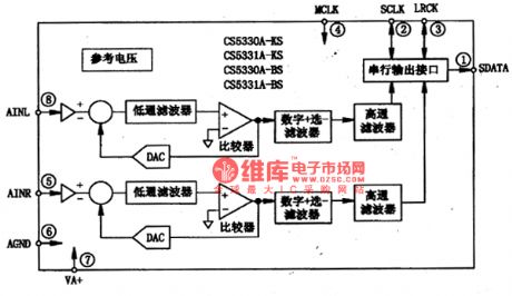
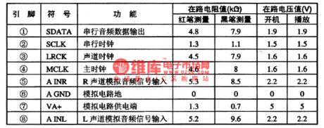
CS5330A, CS5331A are CMOS stereo players with 18 bit resolution which are produced by crystal company, they are widely used in DVD player.
1, functional characteristics
The sampling hold circuit, D∑A/D transformation circuit, digital one of ten filiter, reference voltage generator, serial output interface and other functions are integrated into a chip by CS5330A, CS5331A integrated circuit, it can change the input imitation audio singal into digital audio singal, the sampling frequency can be 32KHz, 44.1 KHz and 48KHz, the internal circuit block diagram of integrated package is shown as figure1, it adopts 8-foot packaging,the pin function and data ofintegrated circuitis shown in chart1.
Fugure1 the internal circuit block diagram of CS5330A, CS5331A integrated package is shown
chart1the pin function and data of CS5330A, CS5331Aintegrated circuit is shown (View)
View full Circuit Diagram | Comments | Reading(732)
The 2.5L motor data sensor, heating oxygen sensor circuit diagram of commercial vehicle
Published:2011/8/10 4:07:00 Author:Nicole | Keyword: commercial vehicle, 2.5L motor , data sensor, heating oxygen sensor

The circuit diagram of shanghai GM Buick commercial vehicle's(GL8) 2.5L motor data sensor, heating oxygen sensor
(View)
View full Circuit Diagram | Comments | Reading(1209)
Pulse dialing seven road infrared remote control circuit diagram
Published:2011/9/26 2:20:00 Author:Rebekka | Keyword: Pulse dialing , seven road infrared remote control


Infrared pulse coding table circuit:
Oscillation frequency:
Infrared receiver control circuit:
(View)
View full Circuit Diagram | Comments | Reading(1182)
8w fluorescent light electronic ballast circuit
Published:2011/8/22 21:13:00 Author:muriel | Keyword: 8w , fluorescent light , electronic ballast
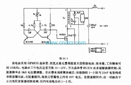
The circuit uses SIPMOS transistors, the advantages of itare control circuit without amplifier, high efficiency, operating frequencycan achieve 100kHz. The voltage of circuit can be10~16V. Switching transistor BUZ20 is controlled by the multivibrator, the oscillation frequency isadjusted by the 5kΩ potentiometer. Transformer with ferrite core, primary winding 1-2 turns and the 33nF capacitorformthe series resonant circuit, when it is blocking, the FET drain voltage is about 60V. In the connected period, the forward resistance of the circuit makes oscillations quickly decay, only about 1~2 times of the battery voltage.
(View)
View full Circuit Diagram | Comments | Reading(3456)
High resistance power distribution circuit
Published:2011/8/22 20:58:00 Author:muriel | Keyword: High resistance, power distribution circuit
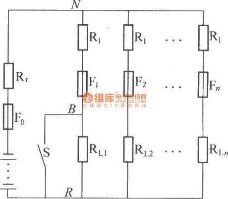
The figure is a circuit diagram of high resistance power distribution. The marked differencebetween it and DZL power distribution is the current limiting resistor R1 which tandem connection specific contact resistance in every shunt load, the general value is 5 times to 10 times of battery internal resistance. If one of the shunts short circuiting, because of the R1 limiting short-circuit current, at the same time the L×di/dt is lesser too. As shown is the voltagechange schematic diagram between N and R. The R1 and Re can make the change of voltagebetween N and R which isallowed in theerror rangeofpower supply system , it makes the loads in the system mutual independence.
(View)
View full Circuit Diagram | Comments | Reading(785)
DK04 Monitoring Module and Computer communication interface circuit
Published:2011/8/22 21:09:00 Author:muriel | Keyword: Monitoring Module, Computer communication interface circuit

As shown in figure, D187 is an UART, it'sRX / TX signalconnectedonoptocoupler N21, N22 and N29, so that put the RS-485communication interface receiver / transmitter D28and microprocessor D211 completely optoelectronicisolated. D197 is a generator, the currently communication rate is 9600bit / s. D189 is another universal asynchronous receiver transmitter. Optocouplers N204 and N206 areisolated the local RS-232 communication port and the microprocessor D211 completely. D209 canmake a single 5V voltage transform into ± l2V communications special RS-232 drive chip.
(View)
View full Circuit Diagram | Comments | Reading(2057)
1kW switching power supply transformer
Published:2011/12/5 1:05:00 Author:May | Keyword: 1kW, switching power supply, transformer

It selects the EE-50 determined according to the skeleton .The first layer N1, the primary coil is wound flatly with 38T, and it is insulated with the second layer. The second layer N2, N3, secondary are wound with 9T, and it is insulated with the third level. N4 fan secondary is wound with 4T. A0, A1, A2 are direct pinouts.
(View)
View full Circuit Diagram | Comments | Reading(1388)
DZW75-48/5050II high frequency rectifier filter circuit
Published:2011/12/4 20:45:00 Author:May | Keyword: high frequency reetifier, filter
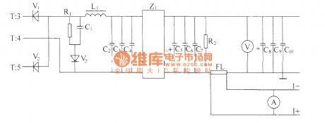
Alternating positive and negative pulse voltage of high-frequency transformer T's secondary induction is rectified by the full-wave rectifier composed of high-power high frequency switching diodes V1,V2, then it is smoothed filtered by L filter composed of inductor and capacitors C2, C3, C4 and Z1 power filter, then it gets 48V volts d.c. output with met the index high and low frequency noise requirements at output end. Impulse width determines the height of output voltage directly. Impulse width is wide, and output voltage is high, impulse width is narrow, output voltage is low. The output end is connected a voltmeter in order to measure display output volts d.c. R2 is leak resistor, and FL is current divider.
(View)
View full Circuit Diagram | Comments | Reading(2548)
DZW75-48/5050II power factor compensation
Published:2011/12/4 20:50:00 Author:May | Keyword: power factor compensation
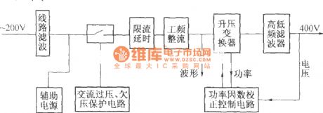
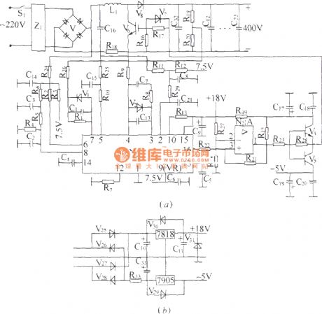
The elementary diagram of DZW75-48/5050II power factor compensation:
DZW75-48/5050II power factor compensation circuit:
In the diagram, (a) is compensation circuit, (b) is auxiliary power supply. It mainly consists of N1, power factor calibration control module and some support circuits. N1 internal circuit consists of saw-tooth wave generator, pulse width modulator and multiple comparator circuit and so on. The frequency of saw-tooth wave generator is determined by out-connected capacitor and resistor. This machine makes the frequency of its output pulse work at 50 kHz, and the width of output pulse is determined by the error voltage after a general comparison treatment. It has three sampling and comparison circuits. V6 is actually an integrated chip containing VMOS tube,enhance diode and rectifier bridge. (View)
View full Circuit Diagram | Comments | Reading(962)
16A thyristor control circuit
Published:2011/4/15 5:45:00 Author:May | Keyword: 16A, thyristor control
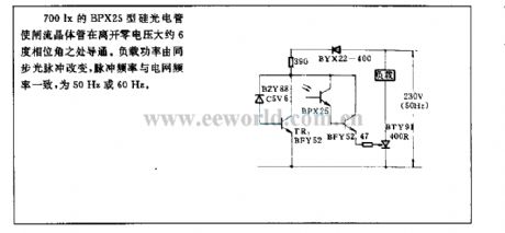
700lx BPX25 type silicon photocell can make thyristor breakover. The breakover place is about 6° phase angle leave to zero voltage . Load power is changed by synchronous optical pulse. Pulse frequency is 50Hz or 60Hz which is the same as grid frequency.
(View)
View full Circuit Diagram | Comments | Reading(1553)
Preamplifier circuit of 1m laser metroscope fringe counter
Published:2011/12/1 20:25:00 Author:May | Keyword: Preamplifier, 1m laser metroscope, fringe counter

The amplification factor of the circuit shown in diagram (a) isis 200, and itsbandwidth is 0~100kHz. And it isused forpreamplification of 1m laser metroscope interference fringe counter.
The circuit shown in diagram (b) is used for preamplication of grating moire fringe subdivision circuit. Its magnification times is 50. Its bandwidth is 0~200kHz. Phase separation of two electric eye outcoming signal is 180° and is amplified by 5G922.
(View)
View full Circuit Diagram | Comments | Reading(1265)
| Pages:375/2234 At 20361362363364365366367368369370371372373374375376377378379380Under 20 |
Circuit Categories
power supply circuit
Amplifier Circuit
Basic Circuit
LED and Light Circuit
Sensor Circuit
Signal Processing
Electrical Equipment Circuit
Control Circuit
Remote Control Circuit
A/D-D/A Converter Circuit
Audio Circuit
Measuring and Test Circuit
Communication Circuit
Computer-Related Circuit
555 Circuit
Automotive Circuit
Repairing Circuit