Basic Circuit
High resistance power distribution circuit
Published:2011/8/22 20:58:00 Author:muriel | Keyword: High resistance, power distribution circuit | From:SeekIC

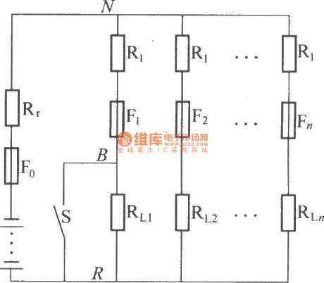
The figure is a circuit diagram of high resistance power distribution. The marked differencebetween it and DZL power distribution is the current limiting resistor R1 which tandem connection specific contact resistance in every shunt load, the general value is 5 times to 10 times of battery internal resistance. If one of the shunts short circuiting, because of the R1 limiting short-circuit current, at the same time the L×di/dt is lesser too. As shown is the voltagechange schematic diagram between N and R. The R1 and Re can make the change of voltagebetween N and R which isallowed in theerror rangeofpower supply system , it makes the loads in the system mutual independence.
Reprinted Url Of This Article:
http://www.seekic.com/circuit_diagram/Basic_Circuit/High_resistance_power_distribution_circuit.html
Print this Page | Comments | Reading(3)

Article Categories
power supply circuit
Amplifier Circuit
Basic Circuit
LED and Light Circuit
Sensor Circuit
Signal Processing
Electrical Equipment Circuit
Control Circuit
Remote Control Circuit
A/D-D/A Converter Circuit
Audio Circuit
Measuring and Test Circuit
Communication Circuit
Computer-Related Circuit
555 Circuit
Automotive Circuit
Repairing Circuit
Code: