
Circuit Diagram
Index 366
TV sound infrared repeater circuit
Published:2012/8/21 2:05:00 Author:Ecco | Keyword: TV sound , infrared repeater
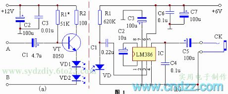
The repeater consists of two parts of the transmitting and receiving. Figure 1 (a) shows the emitting schematic. The frequency discriminator sound ( audio ) signal is amplified by the transistor VT to promote infrared emission tube. Since the emission intensity of the emission tube is proportional to the current, the infrared light emitted by VD1, VD2 is modulated by the audio signal. In order to prevent distortion, VD1, VD2 must set a certain bias. Figure 1 (b) shows the receiving schematic diagram. The circuit uses an audio amplifier IC LM386. VD is the infrared receiver. When the audio signal is irradiated onto VD by modulated infrared light, it will produce the electrical signal which is the same with audio signal on two ends, then it is coupled to IC for amplification by C1.
(View)
View full Circuit Diagram | Comments | Reading(2186)
The automatical switch for TV aural transmitter
Published:2012/8/21 1:43:00 Author:Ecco | Keyword: automatical switch , TV , aural transmitter
The principle: when the TV is turned on, it will generate a strong electromagnetic field around TV, the electromagnetic field is mainly generated by the line scanning system of the television kinescope. TV line scanning frequency is 15.625kHz. So compared to the AC mains, the frequency is higher. As long as detecting the electromagnetic field, it will complete the task by turning on the power switch of broadcast system. In order to make the circuit simple without higher cost, electronic switch for the circuit is served by FET VT. Because the required driving power FET is minimal, it does not need drive current almost. The magnet coil L absorbes to open the TV, then the energy of the electromagnetic field will be generated around the TV.
(View)
View full Circuit Diagram | Comments | Reading(988)
A long-range FM transmitter circuit (500M)
Published:2012/8/21 2:41:00 Author:Ecco | Keyword: long-range , FM , transmitter, 500M
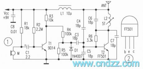
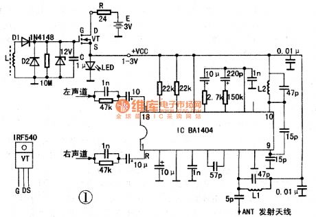
In the circuit shown as Figure 1, the dedicated launch tube T2 and its peripheral components form a high-frequency oscillator with frequency range in 88 ~ 108MHz. The audio signal is picked up by electret microphone and amplified firstly by T1, then the amplified low-frequency signal modulates the high frequency carrier. If the electret microphone M disconnects, the output end connects player to send the music signal. Dedicated tube T2 for RF Transmitter selects FF501 which uses standard T0-92 package ( like the 9000 series of transistors ), and the shape and pin arrangement are shown in Figure 2, and ICM is 45mA, fT is greater than 1.3GHz, VCEO is 13V. The advantages of a dedicated tube include good consistency, greater RF output power, adjustment of circuit, FF501 can fully work in the higher frequency band.
(View)
View full Circuit Diagram | Comments | Reading(3250)
Wireless microphone circuit with NAND gate
Published:2012/8/19 21:17:00 Author:Ecco | Keyword: Wireless microphone, NAND gate
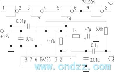
74LS04 is a TTL integrated circuit, there are six single-end input NAND gates. Three NAND gates can form an oscillator. When the power supply voltage is 5V, the oscillation frequency is approximately 90MHz; When supply voltage drops, frequency reduces; when supply voltage rises, frequency increases. Of course, the oscillation amplitude will also change, but has little effect. In this way, people can use the way bu changing the power supply voltage to adjust the frequency ( FM ). The specific approach is to use an audio amplifier IC BA328's output as its power supply. BA328 is a recording head amplifier.
(View)
View full Circuit Diagram | Comments | Reading(1346)
Sensitive photoswitch circuit composed of phototransistor
Published:2012/8/20 0:57:00 Author:Ecco | Keyword: Sensitive photoswitch , phototransistor
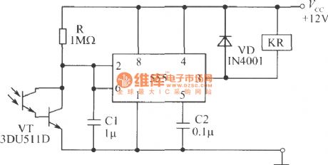
As shown in the figure, the circuit uses Darlington phototransistor sensing elements, so it is more sensitive to low light. It is suited to the detect the reflected light signal. After Darlington photodiodes in the circuit get light, its internal resistance is reduced, so that the potential of pin 2 drops, when it is reduced to (1/3) Vcc, the output of pin 3 is in high level, then the relay releases.
(View)
View full Circuit Diagram | Comments | Reading(1416)
Light trigger switch composed of phototransistor
Published:2012/8/20 1:00:00 Author:Ecco | Keyword: Light , trigger, switch , phototransistor
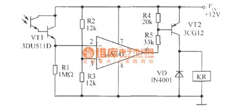
As shown in figure, the circuit uses Darlington phototransistor and op amp, sovery faint light also can make the circuit flip. When R1 and photodiode's positions arereversed, and the op-amp inverting and noninverting input ends are reversed, the circuit can be modified for dark trigger switch.
(View)
View full Circuit Diagram | Comments | Reading(1306)
New punch program controller circuit
Published:2012/8/20 0:52:00 Author:Ecco | Keyword: New punch , program controller


The device is develped in the process of transformation of the old-fashioned punch. It is suitable for punching and cutting the ribbon steel - based products, and it has the advantages of simple, reliable, anti-interference, automatically processed products with the optical signal. The device's circuit is shown below. The listening and reading structure with Optical signal is composed of two 6V ~ 8V bulbs (without condenser ) and two photodiodes and its attachments. Its schematic diagram is shown below. Optical signal is generated by a stick of 1.5mm thick black tape. Information location of each program is shown below.
(View)
View full Circuit Diagram | Comments | Reading(585)
Language circuit controlled by phototransistor
Published:2012/8/19 22:50:00 Author:Ecco | Keyword: Language circuit , phototransistor

It consists of the light control switch and 35 voice IC. In the figure, photosensitive transistor VT1 and crystal transistor VT2, resistors R1 , R2, R3 and capacitors C1 , C2 , etc. constitute the light control switch circuit. Voice integrated circuit IC, transistor VT3 and resistors R4, R5 , etc. constitute a voice amplification circuit. Under the usual light source, VT1 showes a low resistance state, VT2 is in saturated conduction state, IC trigger side-pin 3 does not work without positive trigger pulse, then speaker keeps silent. When VT1 is obscured by the object, it will generate a negative pulse voltage which is coupled to VT2 base through C1, leading to VT2 into the cut-off state, then IC gets a positive trigger pulse to work, and the output audio signal is amplified through VT3 to promote the speaker emit sound.
(View)
View full Circuit Diagram | Comments | Reading(1041)
Light-operated switch circuit
Published:2012/8/19 22:12:00 Author:Ecco | Keyword: Light-operated switch
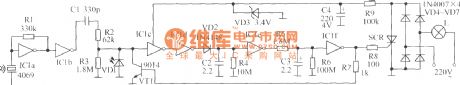
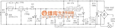
As shown in figure, under normal conditions, the AC voltage passes incandescent, VD4 ~ VD7 bridge rectifier, voltage divider circuit composed of resistor R9 and regulator circuit composed of VD3, C4 to form a loop, the loop current is less than 0.9 mA, power consumption is less than 0.2W, then lights are not bright. When sound sensitive components receive acoustic, acoustic signal is converted into electrical signal, then it passes IC1a, IC1b to make two-stage amplification, and the coupling capacitor C1 will remove the interference signal generated by the low-frequency vibration. When the ambient light is strong, the signal is bypassed by photosensitive diode VD1, and it won't be output for following stage; when the ambient light is weak, VD1 is open, pre- output acoustic signal is amplified by IC1c and 1C1d, VD2, C2, R4 form rectifier and filter circuit to rectify audio signal output by IC1d into a DC signal.
(View)
View full Circuit Diagram | Comments | Reading(894)
Long-range FM radio transmitter circuit
Published:2012/8/19 20:46:00 Author:Ecco | Keyword: Long-range , FM , radio transmitter

In the circuit shown as Figure 1, the special launch tube T2 and its peripheral parts form a high-frequency oscillator with frequency in the range of 88 ~ 108MHz. The electret microphone picks up the audio signal, then the signal is amplified by T1, then the amplified low frequency signal makes modulation for high-frequency carrier. If the electret microphone M disconnects, the input end connects cassette player, and it can transmit music. The RF transmitter dedicated tube T2 chooses FF501 which uses a standard T0-92 package (like the 9000 series of transistors ) , shape, and pin arrangement is shown in Figure 2. The dedicated tube has the advantages of good consistency, the RF output power is greater, and the circuit is easy to adjust, and the FF501 also can work at a higher frequency band.
(View)
View full Circuit Diagram | Comments | Reading(3243)
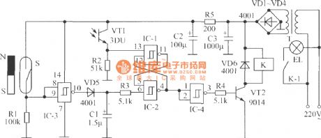
Power-saving corridor lights circuit
Published:2012/8/19 23:02:00 Author:Ecco | Keyword: Power-saving , corridor lights
It is composed of rectifier circuit (diodes VD4 ~ VD7), buck and filter circuit (R10 and C4), control switch VS on the lights H ( VS gets breakover, H is lit ; VS gets shutdown, the H is turned off), light control circuit ( photodiode VD1, inverters F3 , F4, , F5 and F6 and transistor VT ), voice control circuit ( sound - electrical conversion piezoelectric ceramic BH, inverter, F1 , F2, F3, the F4 , F5, F6 and VD3 , C3, R8) and other components.
(View)
View full Circuit Diagram | Comments | Reading(1188)
Burglar alarm circuit composed of photodiode
Published:2012/8/19 22:36:00 Author:Ecco | Keyword: Burglar alarm , photodiode

The alarm is mounted in a drawer. If the thief opens your drawer at night, the alarm will send the souud of ow - ow to warn thieves, and they will dare to start. Photosensitive diode VD, transistor VT1 and resistor R1 form a light control switch; integrated circuit IC, transistor VT2 and speaker YD form the alarm circuit. IC uses the KD-9561 four-tone analog alarm audio Manifold. VT1 and VT2 select 3DG201 silicon transistor with β value being greater than 60. VD selects 2CU photodiode. R1 and R2 use 1W carbon film resistors. YD uses 2.5 inches of electric speaker with impedance in 8Ω. Power select 3 and 5 battery. K selects small, self-resetting and normally closed contact button switch.
(View)
View full Circuit Diagram | Comments | Reading(2380)
Frequency and time signal generator circuit
Published:2012/8/15 22:38:00 Author:Ecco | Keyword: Frequency , time, signal, generator

The circuit uses a 7490 four asynchronous counter (including four flip-flopS ) to form two-frequency divider and five-frequency divider by an external programmer. The time-base circuit is compoaed of two NAND gates and crystal, and the divider uses 13-position switch S to choose different frequency. The output voltage has a TTL- level, which is approximately 3.8V.
(View)
View full Circuit Diagram | Comments | Reading(1570)
0-500 degree K thermocouple temperature measurement circuit
Published:2012/8/15 23:06:00 Author:Ecco | Keyword: 0-500 degree , K , thermocouple , temperature measurement
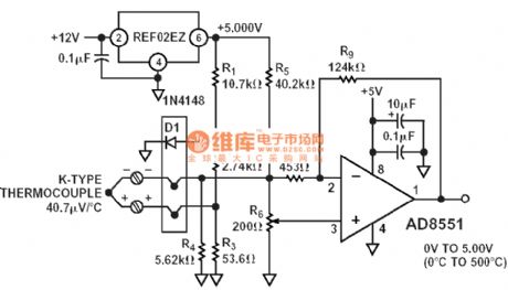
View full Circuit Diagram | Comments | Reading(3940)
Light-operated potentiometer circuit composed of phototransistor
Published:2012/8/19 22:58:00 Author:Ecco | Keyword: Light-operated, potentiometer , phototransistor

Light-operated potentiometer shown as the figure uses the laser pointer for light source to reflect light to photodiode VT1, then the channel resistance reduces, the volume increases; if the irradiation on VT2 reduces, the volume declines, therefore to achieve light-operated volume adjust. Every time you turning on the potentiometer, the VT3 tube's G potential is 0V, the channel resistance is in the maximum value, the volume will be kept the minimum value. The figure shows a mono, if you need to control multiple channels, you only need to connect FET G pole in parallel. The VT3 selects 3DJ6F or similar FET. VT1, VT2 is available to use commercial NPN photodiodes, C1, , C2 , C3 use 6.3μF/25V tantalum electrolytic capacitors. Resistor selects 1/8W metal film resistor.
(View)
View full Circuit Diagram | Comments | Reading(1493)
Gated light switch circuit composed of phototransistor
Published:2012/8/19 22:44:00 Author:Ecco | Keyword: Gated light , switch , phototransistor
When people go home at night, they need to find the light switch in the dark after opening the door; or go out at night, they need to turn off the lights in the dark after locking the door. These occasions bring some inconvenience. Gated light switch circuit shown as the figure can turn on the indoor lights automatically when you go home to open the door at noght; or when you go outside at night, the corridor lights can be turned on automatically with delay 40s, so the circuit can bring you convenience. Charged lamp is not lit during the day. The whole circuit is composed of gated switch, light control switch, delay circuit, the RS flip-flop, implementation circuit and power circuit.
(View)
View full Circuit Diagram | Comments | Reading(1132)
Seal machine control circuit
Published:2012/8/19 22:31:00 Author:Ecco | Keyword: Seal machine , control


(1) It can prevent the program into an infinite loop. In order to improve the system's interference to prevent the program to enter an infinite loop, the system uses the WATCHDOG circuit composed of the counter. 555 is connected as multivibrator with cycle in t0; 74LS93 is connected as hexadecimal counter, when it counts to 8th pulse, QD side becomes high, microcontroller uses P3.7 output to clear pulse. If the cleared pulse interval is shorter than the eight pulse cycle, the counter will never be less than 8, and the QD side keeps low. When CPU receives interference and falls into infinite loop, it can not send reset pulse, the counter will soon count to 8, then QD side goes high immediately, but differential circuit C2 , R3 can output a positive pulse to make CPU is reset.
(View)
View full Circuit Diagram | Comments | Reading(1238)
Ultrashort wave tuner circuit with M0S prestage
Published:2012/8/19 22:01:00 Author:Ecco | Keyword: Ultrashort wave , tuner, M0S prestage
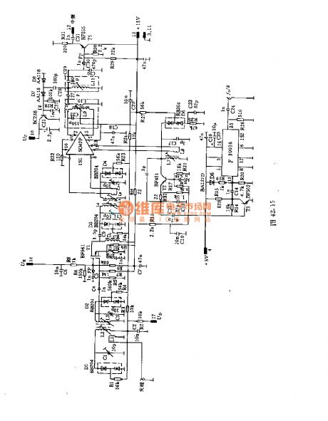
This circuit uses a dual - loop input with band-pass filter to make great prestage selection. It uses MOS prestage and followed ring mixer IC to make high signal intensity. It connects a dual-loop-pass filter between prestage and ring mixer stage in order to achieve good image frequency selection.The main coil data:L1 : o.5mm copper enameled wires with 1 turns;L2, L3, L5:0.8mm copper and silver wires with 5 turns ;L4 : 6 turns , L5 : 5 turns. L4, L5 are 0.8mm copper and silver wires;L6 : 2 turns , L7: 7 turns , L8 : 2 turns , L9 : 12 turns . L6 ~ L9 are 0.5mm copper enameled wires;L9: 12 turns , L10: 2 turns , L11: 12 turns . L9 ~ L11 are copper enameled wires.
(View)
View full Circuit Diagram | Comments | Reading(1056)
Transistors UHF tuner circuit
Published:2012/8/19 21:48:00 Author:Ecco | Keyword: Transistors , UHF, tuner

In the circuit, the adjustable prestage is composed of transistor AF279, and the natural oscillation mixer stage consists of transistor AF280. The power circuit is installed on the board with copper coating. The main coil data:L1, L3, L8, L9: eight turns, the coil uses 0.35mm copper enameled wire with diameter in 3mm;L2 : 3 turns, L10 : 15 turns, L11: 15 turns. L2 , L10, L11 use 0.35mm copper enameled wire with coil diameter in 4.3mm.L12: 5 turns , L13, : 4.5 turns . L12 , L13 use 0.35mm of copper enameled wire with coil diameter in 3.5mm.
(View)
View full Circuit Diagram | Comments | Reading(2799)
Numerical control machine PLC circuit with HK-1 Hall approach switch
Published:2012/8/16 0:56:00 Author:Ecco | Keyword: Numerical control machine , PLC circuit, Hall , approach switch
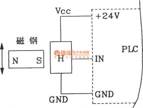
This circuit can also be used on numerical control machine programmable controller (PLC), andits accuracy is up to 0.02mm; it also canbe used for high - speed punch, material sending and cutting, stroke control of complex pattern mold.
(View)
View full Circuit Diagram | Comments | Reading(864)
| Pages:366/2234 At 20361362363364365366367368369370371372373374375376377378379380Under 20 |
Circuit Categories
power supply circuit
Amplifier Circuit
Basic Circuit
LED and Light Circuit
Sensor Circuit
Signal Processing
Electrical Equipment Circuit
Control Circuit
Remote Control Circuit
A/D-D/A Converter Circuit
Audio Circuit
Measuring and Test Circuit
Communication Circuit
Computer-Related Circuit
555 Circuit
Automotive Circuit
Repairing Circuit