Basic Circuit
DZW75-48/5050II high frequency converting circuit
Published:2011/12/4 20:29:00 Author:May | Keyword: high frequency converting | From:SeekIC


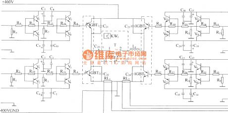
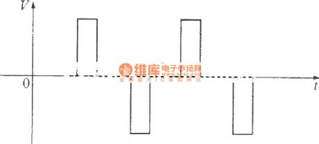
High frequency converter adopts full bridge structure. IGBT in four arms are separately driven by four drivers which are mutual isolated. Their working power supply is 300V. Under the effect of drive pulse, high frequency switching tubes on the two crosses are turned on at the same time, or cut off at the same time, thereby getting high frequency pulse voltage at main transformer’s first and second coils, in order to achieve high frequency conversion of DC/AC. When both 1# and 4# drive pulses are in positive potential, IGBT1, IGBT4 are turned on at the same time, at this time, both the drive pulse of IGBT2 and IGBT3 are in negative potential, cut off reliably, the first coil of main transformer T will have current, the current direction is from 1 end to 2 end, and the primary induced voltage is set to positive pulse, and its width is about 300V.
Reprinted Url Of This Article:
http://www.seekic.com/circuit_diagram/Basic_Circuit/DZW75_48_5050II_high_frequency_converting_circuit.html
Print this Page | Comments | Reading(3)

Article Categories
power supply circuit
Amplifier Circuit
Basic Circuit
LED and Light Circuit
Sensor Circuit
Signal Processing
Electrical Equipment Circuit
Control Circuit
Remote Control Circuit
A/D-D/A Converter Circuit
Audio Circuit
Measuring and Test Circuit
Communication Circuit
Computer-Related Circuit
555 Circuit
Automotive Circuit
Repairing Circuit
Code: