Filter Circuit
DZW75-48/50(50II) high frequency rectifying filtering circuit
Published:2011/11/23 1:27:00 Author:May | Keyword: high frequency rectifying, filtering | From:SeekIC
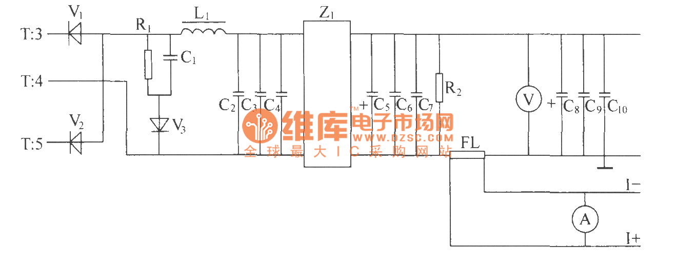
Positive and negative alternation pulse voltage of high frequency transformer T’s secondary induction pass full wave rectifier composed of high frequency switching diodes V1, V2, then pass L power line filter composed of L1 inductor and capacitor C2, C3, C4 and Z 1 :power supply filter and other smoothing filters,then the output end gets 48V DC voltage output with high and low frequency noise to meet the index demand. The pulse width isdirectly decided bythe output voltage. When the pulse width is wide, the output voltage will be high; if the pulse width is narrow, output voltage islow. In order to measureanddisplay output DC voltage, we can parallel connect a voltmeter in output end. R2 is the leak resistor. FL is thecurrent divider. The voltage value in the justify of FL also can be uses as output current sampling signal and itcan besent to stabilize voltage and limit current. R1, C1 and V3 make up the RCD absorber circuit to absorb overshoot voltage of secondary.
Reprinted Url Of This Article:
http://www.seekic.com/circuit_diagram/Basic_Circuit/Filter_Circuit/DZW75_48_5050II_high_frequency_rectifying_filtering_circuit.html
Print this Page | Comments | Reading(3)

Article Categories
power supply circuit
Amplifier Circuit
Basic Circuit
LED and Light Circuit
Sensor Circuit
Signal Processing
Electrical Equipment Circuit
Control Circuit
Remote Control Circuit
A/D-D/A Converter Circuit
Audio Circuit
Measuring and Test Circuit
Communication Circuit
Computer-Related Circuit
555 Circuit
Automotive Circuit
Repairing Circuit
Code: