
Circuit Diagram
Index 2077
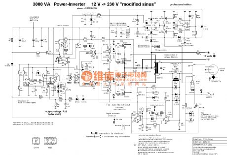
The circuit diagram of inverter with 12V-230V 1KW
Published:2011/3/22 21:03:00 Author:muriel | Keyword: inverter, 12V-230V, 1KW, TL081, CD4013, CA3130, BCY79, μA741, BS250, 2N7000
View full Circuit Diagram | Comments | Reading(3423)
SHANGHAI GM BUICK(Excelle) saloon car automatic transmission circuit diagram(two)
Published:2011/4/18 0:53:00 Author:muriel | Keyword: SHANGHAI GM BUICK(Excelle), saloon car , automatic transmission

Figure SHANGHAI GM BUICK(Excelle) saloon car automatic transmission circuit diagram(two) (View)
View full Circuit Diagram | Comments | Reading(466)
SHANGHAI GM BUICK(Excelle) saloon car automatic transmission circuit diagram(one)
Published:2011/4/18 0:51:00 Author:muriel | Keyword: SHANGHAI GM BUICK(Excelle) , saloon car , automatic transmission

Figure SHANGHAI GM BUICK(Excelle) saloon car automatic transmission circuit diagram(one) (View)
View full Circuit Diagram | Comments | Reading(493)
SHANGHAI GM BUICK(LaCROSSE) saloon car motor driven seat circuit diagram(two)
Published:2011/4/18 1:07:00 Author:muriel | Keyword: SHANGHAI GM BUICK(LaCROSSE), saloon car, motor driven seat

SHANGHAI GM BUICK(LaCROSSE) saloon car motor driven seat circuit diagram(two) is as shown
(View)
View full Circuit Diagram | Comments | Reading(518)
The connection circuit diagram of speaker and high bass frequency divider
Published:2011/4/14 2:19:00 Author:Ecco | Keyword: speaker , high bass frequency divider

The connectionmethod of speaker and high bass frequency divider is shown as the chart 212: The inductors and the bass speakers connect in series, capacitors and the tweeter connect in series. The capacitor is used as AC capacitor that made by two small-capacity capacitors, inductance coil can be self-made. If it's a 10-inch box speaker, and the power is between 5 ~ 10W, the inductance coi could choose the size of 0.85mH. If chosen an empty skeleton with the core diameter in 3cm, it can be made by the line with the diameter in 0.8 to 1.0 mm and rolled with 300 laps.
(View)
View full Circuit Diagram | Comments | Reading(502)
The five-storey light switch controlling method circuit diagram
Published:2011/4/7 3:20:00 Author:Ecco | Keyword: five-story light , switch controlling method

View full Circuit Diagram | Comments | Reading(482)
Connection circuit diagram of four-wire ballast in fluorescent
Published:2011/4/7 3:17:00 Author:Ecco | Keyword: Four-wire , fluorescent, ballast connection

Four-wire ballast connection of fluorescent
There are four lead wires in four-wire ballast, including main and auxiliary coils. The connection of two lead wires in main coil is the same with second-line ballast, both of them connect between the lamp and power supply in series. The two lead wires in auxiliary coil connect between the starter and the tube in series to help starting. As the number of turns in secondary coil is few, AC impedance is small, if it is mistakenly connected to the main road of the power supply, it will burn lamps and ballasts. Therefore, before the rectifier accessing in circuit, you must see the connection description, to distinguish main and auxiliary coils. Multimeter can also be used as detecting, the higher resistance of coil is main coil. (View)
View full Circuit Diagram | Comments | Reading(2143)
74 series digital circuit of 74H15 74LS15 3 input nand gate
Published:2011/4/5 22:42:00 Author:Ecco | Keyword: digital circuit, 3 input , nand gate
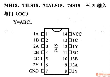
74H15, 74LS15, 74ALS15, 74S153 input nand gate(OC)
(View)
View full Circuit Diagram | Comments | Reading(1853)
74 series digital circuit of 74S64 74F64 input and-or-invert gate
Published:2011/4/5 22:48:00 Author:Ecco | Keyword: digital circuit , input , negater
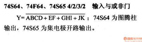
74S64, 74F64, 74S64 4/2/3/2input and-or-invert gate.
74S64 is totem pole output, 74S65 is open-connector output. (View)
View full Circuit Diagram | Comments | Reading(682)
74 series digital circuit of 74H71 input J - K master-slave flip-flop
Published:2011/4/5 22:44:00 Author:Ecco | Keyword: digital circuit, input J - K , master-slave flip-flop
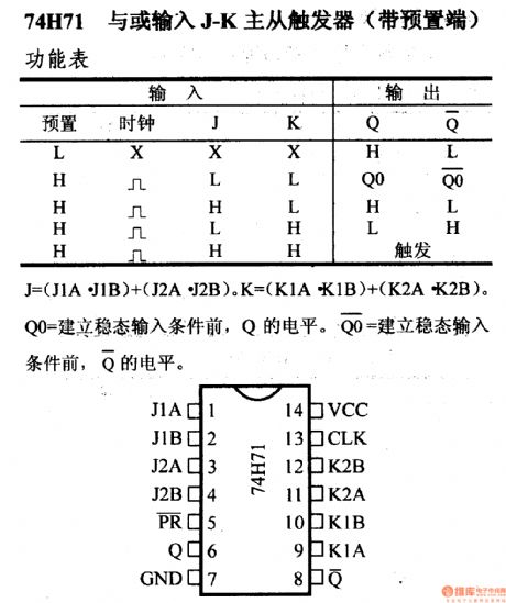
74H71 input J - K master-slave flip-flop (with preset terminal)
The level of Qo is equal to Q before eatablishing steadystate input. (View)
View full Circuit Diagram | Comments | Reading(761)
74 series digital circuit of 74LS71 input R-S master-slave flip-flop
Published:2011/4/5 22:44:00 Author:Ecco | Keyword: digital circuit, input R-S , master-slave flip-flop
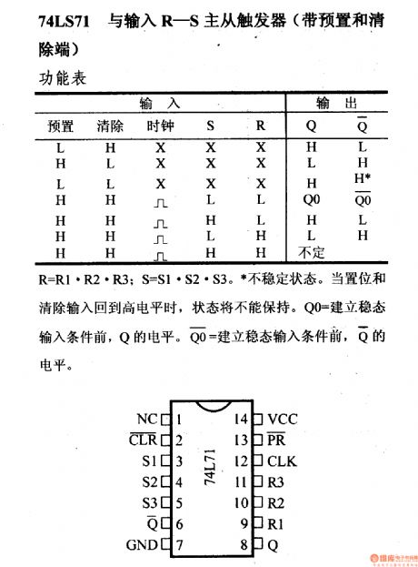
74LS71 input R-S master-slave flip-flop( with preset and remove terminal )
Unsteady state. When the preset and remove terminal return in high level, the state could not be kept. And the level of Qo is equal to Q before eatablishing steadystate input. (View)
View full Circuit Diagram | Comments | Reading(2977)
74 series digital circuit of 7474 double D type positive edge flip-flop
Published:2011/4/5 22:44:00 Author:Ecco | Keyword: digital circuit , double D type , positive edge , flip-flop

7474, 74H74, 74F74, 74ALS74, 74L74, 74LS74A, 74S74, 74HC74, 74C74double D type positive edge flip-flop(with preset and remove terminal)
Unsteady state. When the preset and remove terminal return in high level, the state could not be kept. And the level of Qo is equal to Q before eatablishing steadystate input. (View)
View full Circuit Diagram | Comments | Reading(4859)
74 series digital circuit of 7476 74H76 double J - K flip-flop(with preset and remove terminal)
Published:2011/4/5 22:44:00 Author:Ecco | Keyword: digital circuit , double J - K , flip-flop
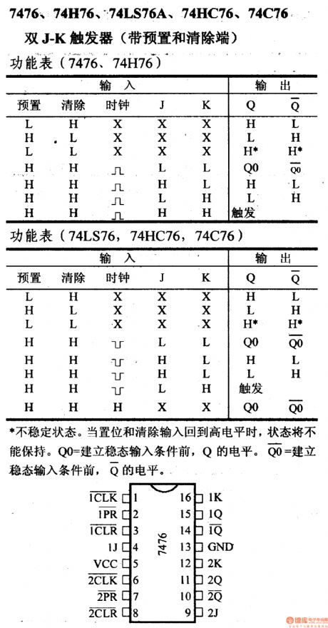
Unsteady state. When the preset and remove terminal return in high level, the state could not be kept. And the level of Qo is equal to Q before eatablishing steadystate input.
(View)
View full Circuit Diagram | Comments | Reading(1892)
The voltage-controlled oscillator with triangular wave and square wave output
Published:2011/4/18 1:59:00 Author:Ecco | Keyword: voltage-controlled oscillator , triangular wave , square wave , output
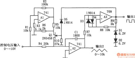
The voltage-controlled oscillator with triangular wave and square wave output is shown as the chart. The circuit is a controlled voltage-controlled oscillator. It has good stability and excellent linearity and a wide frequency range. The circuit has two output terminals, one is the square wave output, and the other one is the triangle wave output. In the figure, A1 is an inverter, A2 is an integrator, A3 is a comparator. The FET Q1 is used to transform integration direction. The reference voltage of comparator is provided by diode D1, D2, The comparing between the output of integrator and reference voltage make the square-wave output. Resistors R5, R6 are used to reduce the drain voltage of Q1 to ensure a large input signal Q1 being fully closed. Resistors R7, R8, and diodes D3, D4 A3 are used to prevent blocking. According to the value of marked components in the figure, the power supply is +15V, the transform coefficient is the 1kHz / V. The circuit has a linearity error less than ± 0.5% in the frequency range of 100:1.
(View)
View full Circuit Diagram | Comments | Reading(1588)
The timing circuit composed of 555
Published:2011/4/18 4:49:00 Author:Ecco | Keyword: timing circuit , 555

View full Circuit Diagram | Comments | Reading(587)
Low power timer composed of 555
Published:2011/4/18 4:41:00 Author:Ecco | Keyword: Low power , timer , 555

View full Circuit Diagram | Comments | Reading(642)
Operation amplifier low-pass filter circuit
Published:2011/4/17 21:08:00 Author:Jessie | Keyword: Operation amplifier low-pass filter

View full Circuit Diagram | Comments | Reading(642)
Operation amplifier venturi filter circuit diagram
Published:2011/4/13 20:18:00 Author:Jessie | Keyword: Operation amplifier, venturi filter
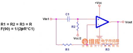
For all frequencies venturi filters are the same gain, but it can change the angle of signals, it also can be used for angle correction circuit at the same time. Circuit has a 90 degrees' phase shift on the signal frequency F,a0 degree's phaseshifton dc, and a 180 degrees' phase shifton the high frequency. (View)
View full Circuit Diagram | Comments | Reading(697)
Operation multi-feedback filter circuit
Published:2011/4/13 21:07:00 Author:Jessie | Keyword: Operation, multi-feedback, filter
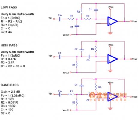
Multi-feedback filteris a universal, low cost and easy implementing filter. Unfortunately, the calculation of designing is a littlecomplex, here without in-depth introduction. Please see the reference which introducts multi-feedback filter in the details. If need a unity-gain Butterworth filter, then this circuit can give a similar result. (View)
View full Circuit Diagram | Comments | Reading(756)
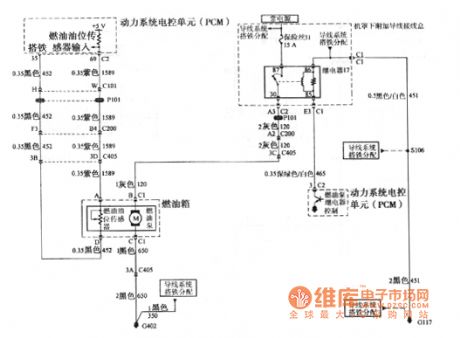
Buick GL8 fuel oil level sensor circuit
Published:2011/4/18 4:35:00 Author:Jessie | Keyword: fuel oil level sensor
View full Circuit Diagram | Comments | Reading(749)
| Pages:2077/2234 At 2020612062206320642065206620672068206920702071207220732074207520762077207820792080Under 20 |
Circuit Categories
power supply circuit
Amplifier Circuit
Basic Circuit
LED and Light Circuit
Sensor Circuit
Signal Processing
Electrical Equipment Circuit
Control Circuit
Remote Control Circuit
A/D-D/A Converter Circuit
Audio Circuit
Measuring and Test Circuit
Communication Circuit
Computer-Related Circuit
555 Circuit
Automotive Circuit
Repairing Circuit