
Circuit Diagram
Index 2066
Four channels interlock control circuit schematic
Published:2011/4/18 6:13:00 Author:Rebekka | Keyword: Four channels, interlock control


Four-channel remote control transmitter interlock circuit diagram.
Four-channel remote control receiver interlock circuit diagram. (View)
View full Circuit Diagram | Comments | Reading(1826)
Anti-jamming radar anti-theft alarm circuit diagram
Published:2011/4/18 6:06:00 Author:Rebekka | Keyword: Anti-jamming , radar anti-theft alarm

Anti-jamming radar anti-theft alarm uses secondary power supply, signal processing circuit. It uses pulse recognition network to suppress the power supply voltage fluctuation, suppress the clutter and other interference factors with a high reliability. (View)
View full Circuit Diagram | Comments | Reading(3048)
Multi-function remote control circuit(400 in 1 and 8 categories 8 compatible with the RM-V701 SONY)
Published:2011/4/18 4:54:00 Author:Rebekka | Keyword: Multi-function remote control,

View full Circuit Diagram | Comments | Reading(523)
Multi-output crystal oscillator
Published:2011/4/19 1:44:00 Author:Ecco | Keyword: Multi-output , crystal, oscillator
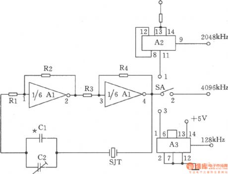
The chart shows the multi-output crystal oscillator. It is mainly composed of three gates of A1, four resistors, two capacitors and a crystal. Rl ~ R4 bias two inverters in the linear range, and they are connected between the pin 4 and pin1 of A1 by the crystal SJT, and they are used to provide feedback loop. It only produces frequency on the fundamental frequency of crystal. The selection of components: capacitor Cl is 15p (vernier capacitor). Resistors Rl, R3 are 220Ω, R2 is 560Ω, R4 is 1.8kΩ, R5 is 1kΩ, the nominal power is l/8W. IC Al is 7404, A2 is the 74LS74, A3 is the 74LS393. Crystal SJT is SW60A-4096kHz. Switch SA is KNX (1 × 3).
(View)
View full Circuit Diagram | Comments | Reading(719)
Square wave and sine wave generator
Published:2011/4/19 1:33:00 Author:Ecco | Keyword: Square wave, sine wave, generator
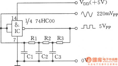
The chart shows the square wave and sine wave generator. It is a clock generator composed of an ordinary inverting gate and a few components, and it can output two waveforms with the same frequency simultaneously: square wave and sine wave. The oscillator can work well in the frequency of 100Hz ~ 10MHz. If using non-buffered output stage 74HCU00 replaces the 74HC00, it will have a better effect. (View)
View full Circuit Diagram | Comments | Reading(2262)
Wireless remote control ceiling fan circuit diagram
Published:2011/4/18 4:52:00 Author:Rebekka | Keyword: Wireless remote control, ceiling fan

Ceiling fan wireless remote control transmitter circuit.
Ceiling fan wireless remote control receiver circuit.
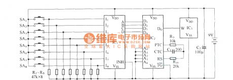
In transmitter circuit:IC1 is line 10-line 4 priority encoder CD40147;IC2 is the digital encoder MC145026;IC3 is the long-wave emission component T630.In receiver circuit:IC1 is a long-wave receiver module T631;IC2 is a digital decoder MC145027;IC3 is a 4-16 line decoder CD4514.
(View)
View full Circuit Diagram | Comments | Reading(6327)
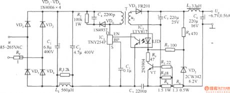
+6.7V, 0.56A Cell phone battery constant-current charger circuit composed of TNY254P
Published:2011/4/19 1:48:00 Author:Ecco | Keyword: +6.7V, 0.56A , Cell phone , battery, constant-current , charger
View full Circuit Diagram | Comments | Reading(2274)
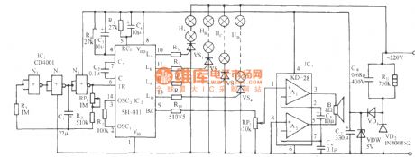
SH-811 festival color lamp with piano music automatic program control circuit
Published:2011/4/19 1:44:00 Author:Nicole | Keyword: festival color lamp, piano music, program control
View full Circuit Diagram | Comments | Reading(488)
SH-818 seven functions color lamp and good quality piano music automatic control circuit
Published:2011/4/19 1:26:00 Author:Nicole | Keyword: color lamp, piano music
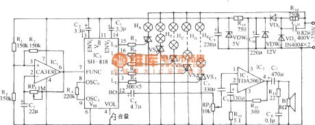
As shown in the figure, it consists of clock beat generator, light control circuit, middle power amplifier and AC depressurization, steady voltage circuit. CA3130(IC1) is a BiMOS single operational amplifier, it with RP1, R3, C1 will from a self-excited oscillator, the oscillation frequency depends on the charge and discharge time of RP1, C1. Its output beat pulse is used as SH-818 function control pulse. (View)
View full Circuit Diagram | Comments | Reading(437)
Simplest bidirectional SCR dimming light circuit
Published:2011/4/19 0:56:00 Author:Nicole | Keyword: bidirectional SCR, dimming light
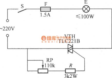
As shown in the figure, this is a simplest bidirectional SCR dimming light circuit, the feature of it is that adding proper trigger pulse or control current to its control pole, it will turn on whether it is AC positive half cycle or negative half cycle, the conduction time depends on the pulse width and gate current. To adjust RP will change the brightness of bulb E. (View)
View full Circuit Diagram | Comments | Reading(813)
Simplest unidirectional SCR dimming light circuit
Published:2011/4/19 0:46:00 Author:Nicole | Keyword: unidirectional SCR, dimming light

As shown in the figure, this is a simplest unidirectional SCR dimming light circuit, the two 3~5A/600V unidirectional SCR are antiparallel, their gates are connected by a 100kΩ potentiometer, then they form a stepless dimmer with 200W load. (View)
View full Circuit Diagram | Comments | Reading(2681)
Showcase or bulletin board timing light controllor circuit(1)
Published:2011/4/18 23:50:00 Author:Nicole | Keyword: showcase or bulletin board, timing light, controllor

As shown in the figure, it is a showcase or bulletin board timing light controllor composed of two electronic tables, the electronic table 1 is used to set everyday lighting up time, the electronic table 2 is used to set everyday turn-off light time. (View)
View full Circuit Diagram | Comments | Reading(438)
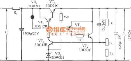
12V regulated voltage power supply circuit with series and parallel connection combination
Published:2011/4/10 20:49:00 Author:muriel | Keyword: 12V , regulated voltage power supply, series and parallel connection combination
View full Circuit Diagram | Comments | Reading(648)
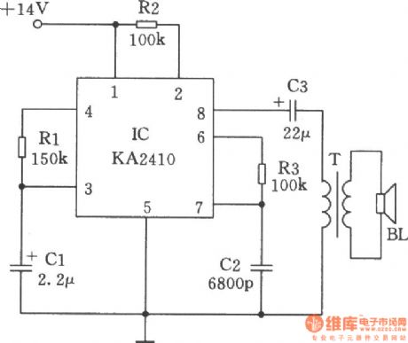
Analog sound generator made by telephone ringing IC
Published:2011/4/19 1:06:00 Author:Ecco | Keyword: Analog, sound generator , telephone ringing , IC
View full Circuit Diagram | Comments | Reading(707)
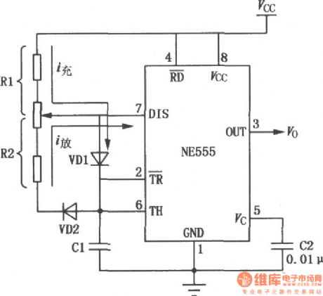
Adjustable duty cycle multivibrator composed of 555
Published:2011/4/19 1:08:00 Author:Ecco | Keyword: Adjustable, duty cycle , 555, multivibrator
View full Circuit Diagram | Comments | Reading(1069)
The acquisition circuit of light isolation data
Published:2011/4/19 1:18:00 Author:Ecco | Keyword: acquisition circuit , light isolation, data
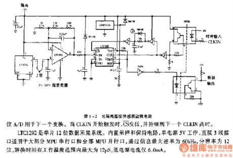
LTC1292 is a monolithic 12-bit data acquisition system. Built-in sample and hold circuit work under 5V single supply. Connecting to wire 3 directly, it is suitable for most serial and parallel interface port of MPU. The maximum rate of passing information is 60kHz, the resolution is 12-bit, the maximum conversion time in the operating temperature range is 12μs, the low current is only 6.0mA.
(View)
View full Circuit Diagram | Comments | Reading(781)
LM317 Adjustable voltage regulator circuit diagram
Published:2011/4/19 1:20:00 Author:Ecco | Keyword: Adjustable, voltage regulator

View full Circuit Diagram | Comments | Reading(3631)
The high voltage electrostatic generator circuit diagram composed of NE555
Published:2011/4/19 1:00:00 Author:Ecco | Keyword: high voltage, electrostatic , generator

The multi-function high-voltage electrostatic generator is based on 555, if matching with high back voltage diode and discharge brush pin, it can be used as a negative oxygen ion generator, ignition, static vacuum cleaner, or high security, etc. 555 and R1, R2, C2 form a multivibrator with non-steady state, the oscillation frequency F = 1.44 / (R1 +2 R2) C2, the argument in the figure is about 20KHZ. After boosted by the transformer T1,then it will get 20KHZ 10KV high voltage on secondary of T1, and it will be 7KV after rectified by D1, the load current can reach 50UA. (View)
View full Circuit Diagram | Comments | Reading(7712)
Relay pull-in timer circuit in time process
Published:2011/4/18 22:30:00 Author:Nicole | Keyword: relay, timer, time process


In figure (a), the circuit has two-stage circuit structures, the timing time is about 0.5~12s, and in figure (b), the range of the timing time is 1~160s.
The parameters of transformer: iron chip: M42/15.7 silicon steel sheet; winding: Φ0.18mm, enameled copper wire 1200turns.
(View)
View full Circuit Diagram | Comments | Reading(1632)
Ni-Cd battery charge circuit composed of TB1004 charge control integrated circuit
Published:2011/4/18 21:06:00 Author:Nicole | Keyword: Ni-Cd battery, charge control


(View)
View full Circuit Diagram | Comments | Reading(809)
| Pages:2066/2234 At 2020612062206320642065206620672068206920702071207220732074207520762077207820792080Under 20 |
Circuit Categories
power supply circuit
Amplifier Circuit
Basic Circuit
LED and Light Circuit
Sensor Circuit
Signal Processing
Electrical Equipment Circuit
Control Circuit
Remote Control Circuit
A/D-D/A Converter Circuit
Audio Circuit
Measuring and Test Circuit
Communication Circuit
Computer-Related Circuit
555 Circuit
Automotive Circuit
Repairing Circuit