Circuit Diagram
Index 2079
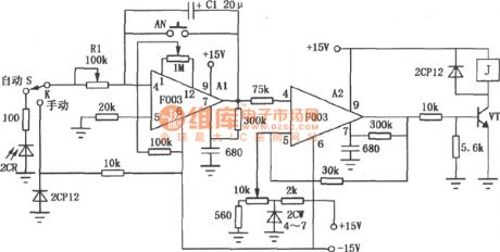
TX03A artificial heart-lung machine circuit
Published:2011/4/18 2:33:00 Author:Ecco | Keyword: artificial , heart-lung, machine
View full Circuit Diagram | Comments | Reading(704)
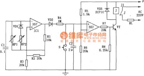
The sleep massager circuit
Published:2011/4/18 2:30:00 Author:Ecco | Keyword: Sleep , massager
View full Circuit Diagram | Comments | Reading(1029)
The negative oxygen ion generator
Published:2011/4/18 2:37:00 Author:Ecco | Keyword: negative, oxygen ion , generator
View full Circuit Diagram | Comments | Reading(836)
Electronic biological wave Physiotherapy apparatus circuit
Published:2011/4/18 2:41:00 Author:Ecco | Keyword: Electronic , biological wave , Physiotherapy apparatus
View full Circuit Diagram | Comments | Reading(1661)
Electrical impulses treatment circuit
Published:2011/4/18 2:42:00 Author:Ecco | Keyword: Electrical impulses , treatment
View full Circuit Diagram | Comments | Reading(836)
Electronic touch game console composed of 555
Published:2011/4/18 2:48:00 Author:Ecco | Keyword: Electronic , touch , game console , 555
View full Circuit Diagram | Comments | Reading(635)
Desk lamp touch switch circuit
Published:2011/4/18 0:59:00 Author:Ecco | Keyword: Desk lamp , touch, switch
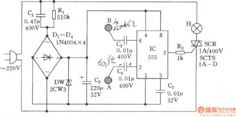
The touch switch circuitis composed of the buck rectifier, voltage regulator and trigger controlling circuits and other components, touching the metal piece A, then the lamp is lit; and then touching the metal B, then the light turns off.The circuit is as shown.
(View)
View full Circuit Diagram | Comments | Reading(2959)
The adjustable voltage-controlled oscillator with large duty cycle
Published:2011/4/18 1:28:00 Author:Ecco | Keyword: adjustable, voltage-controlled oscillator , large duty cycle
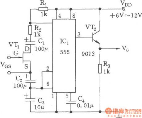
Voltage-controlled oscillator circuit is as shown. 555, R1, R2, C1 ~ C3 and VT1 form a voltage-controlled multivibrator, FET (JFET) VT is voltage-controlled resistor, which can change the impedance between VT-drain (D) and source (S) by changing the gate-source voltage VGs. The coupled capacitors C1、C2 are connected to D,S of VT, they are used to prevent the influence from rest of the circuit of the DC voltage on the JFET. If making coupling capacitors have no effect on the charging and discharging time of time base circuit, the size of C1, C2 should be 10 times of the timing capacitor C3. The advantages of this circuit: the changing of gate-source voltage VGs can make an adjustable variable resistor Rx (can be as large as several hundred kΩ), then it gets the changing of duty cycle and the cycle.
(View)
View full Circuit Diagram | Comments | Reading(2661)
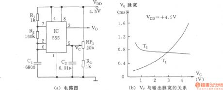
Voltage controlled oscillator with Vc-side controlling duty cycle
Published:2011/4/18 0:54:00 Author:Ecco | Keyword: Voltage controlled oscillator , Vc-side, controlling , duty cycle
View full Circuit Diagram | Comments | Reading(550)
The multivibrator circuit with variable pitch
Published:2011/4/18 0:40:00 Author:Ecco | Keyword: multivibrator , variable pitch
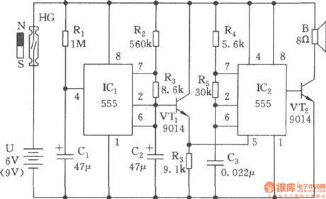
The multivibrator circuit with variable pitch is composed of two 555 time base circuits, it can issue wave of oscillation changed in 400~2500Hz, and its sound is similar to the sound of the public security police. The circuit consists of power-delay, low-frequency oscillator and the modulation generator.
(View)
View full Circuit Diagram | Comments | Reading(748)
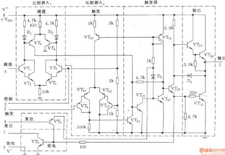
CA555 equivalent circuit produced by Radio Corporation of America
Published:2011/4/18 0:50:00 Author:Ecco | Keyword: equivalent circuit , Radio Corporation of America
View full Circuit Diagram | Comments | Reading(480)
555 Equivalent function circuit diagram
Published:2011/4/18 0:47:00 Author:Ecco | Keyword: 555, Equivalent function
View full Circuit Diagram | Comments | Reading(684)
MC1594 AC voltage multiplier circuit
Published:2011/4/14 22:02:00 Author:Jessie | Keyword: AC voltage, multiplier

This circuit is composed by four quadrant multiplier MC1594, the circuit issimple, the accuracy is a bit poor. In order to make the circuit works in linear area, input resistance R1 and R2's values depend on the input voltage's value. R1 equals to V1 multiplied by 6, R2 equals to V2 multiplied by three. If V1=V2=3V, then R1=18kΩ, R2=9kΩ.When there aredifferent input voltages, generally R1=52kΩ, R2=30kΩ, but that would make precision and linearity fell. The relationship of input and output is Vo=V1V2/10. (View)
View full Circuit Diagram | Comments | Reading(1011)
Digital pulse width measurement circuit composed of CD4518 and CD4069
Published:2011/3/28 1:53:00 Author:may | Keyword: Digital pulse width measurement

Digital pulse width measurement circuit is show in the diagram. It adopts a 100KHz reference frequency, count at the range of measured signal pulse width, the product of count value and resolving capability present measured signal pulse width value, display through four digital seven-segment LED. The resolving capability is 10μs, its maximum measure width is 99.99ms. IC2, IC3 is double BCD up counter CD4518; IC4~IC7 is BCD seven-segment latch/ decoder/ driver CD4511.
(View)
View full Circuit Diagram | Comments | Reading(8135)
Family karaoke lighting control circuit composed of 5GM168
Published:2011/3/23 23:24:00 Author:may | Keyword: 5GM168

The design method of family karaoke lighting control is varied, here introduced control circuit is a application circuit with four load light ouput, jump circulate, speed controlable. Light jump speed change along with microphone received voice signal strong or weak, voice signal more strong, light jump faster, or speed is slow. Family karaoke lighting control circuit is shown in the diagram. This circuit mainly consists of power supply circuit, control circuit and audio-frequency amplifier.
(View)
View full Circuit Diagram | Comments | Reading(1096)
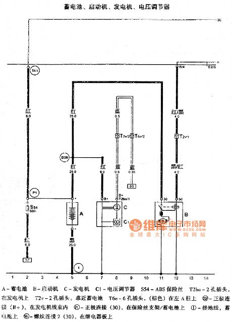
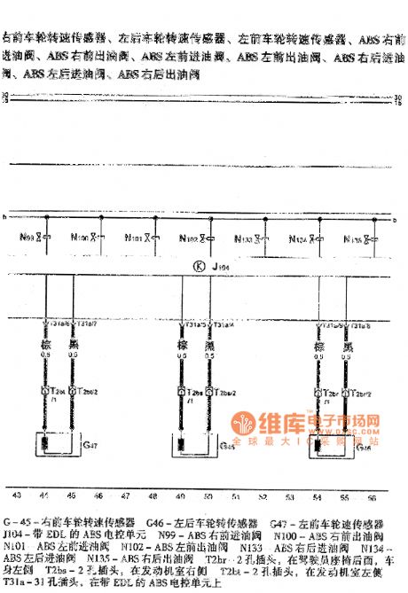
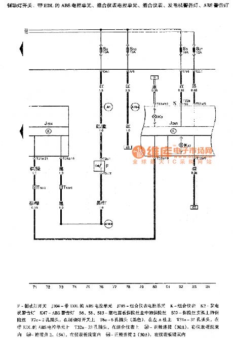
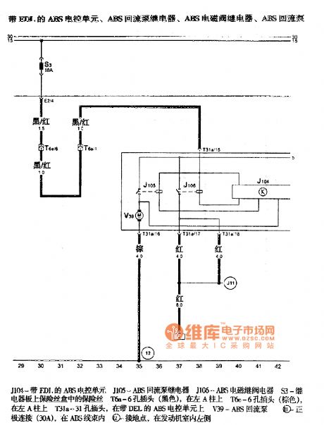
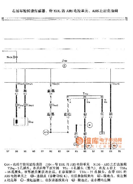
Gaoer ABS circuit
Published:2011/4/14 22:24:00 Author:Jessie | Keyword: ABS
View full Circuit Diagram | Comments | Reading(669)
Rongshen YB35-65A YB45-80A YB55-95A insulation automatic electric pressure cooker circuit
Published:2011/4/14 22:26:00 Author:Jessie | Keyword: insulation, automatic, electric pressure cooker
View full Circuit Diagram | Comments | Reading(690)
Ae timer circuit with op-amp 5G28
Published:2011/4/18 1:54:00 Author:Jessie | Keyword: Ae timer, op-amp
View full Circuit Diagram | Comments | Reading(1265)
Ae timer circuit with F003 op-amp
Published:2011/4/18 1:51:00 Author:Jessie | Keyword: Ae timer, op-amp
View full Circuit Diagram | Comments | Reading(712)
Power line load V, I and P isolation detection circuit
Published:2011/4/18 0:51:00 Author:Jessie | Keyword: Power line load V, I and P, isolation detection
View full Circuit Diagram | Comments | Reading(522)
| Pages:2079/2234 At 2020612062206320642065206620672068206920702071207220732074207520762077207820792080Under 20 |
Circuit Categories
power supply circuit
Amplifier Circuit
Basic Circuit
LED and Light Circuit
Sensor Circuit
Signal Processing
Electrical Equipment Circuit
Control Circuit
Remote Control Circuit
A/D-D/A Converter Circuit
Audio Circuit
Measuring and Test Circuit
Communication Circuit
Computer-Related Circuit
555 Circuit
Automotive Circuit
Repairing Circuit


