
Circuit Diagram
Index 2060
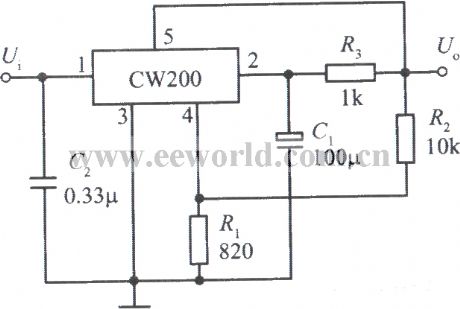
The standard application circuit of 5 end adjustable output voltage integrated regulator CW200
Published:2011/4/19 1:34:00 Author:muriel | Keyword: standard application circuit , 5 end, adjustable , output voltage, integrated , regulator

View full Circuit Diagram | Comments | Reading(389)
10Mb optical data circuit
Published:2011/4/18 2:33:00 Author:muriel | Keyword: 10Mb, optical data circuit

The optical data circuit is used for between teletypewriter and micro place view device, it uses the broadband fiber optic to transmit dataat the rate of 10Mb. Receiver input end use C3808 PIN photosensitive diode.
(View)
View full Circuit Diagram | Comments | Reading(533)
The expanding RAM of 8515
Published:2011/4/10 20:49:00 Author:muriel | Keyword: 8515, Expand RAM

View full Circuit Diagram | Comments | Reading(559)
12V/5A regulated power supply circuit
Published:2011/4/18 2:44:00 Author:muriel | Keyword: 12V/5A , regulated power supply
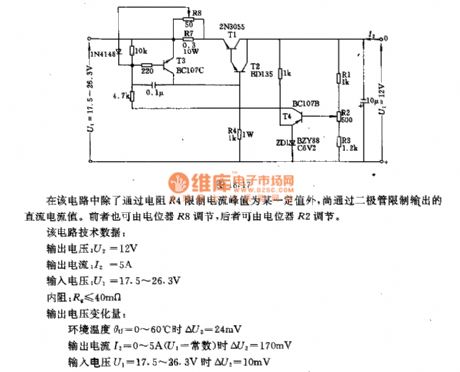
In the circuit the current peak value is a certain value gothrough the limit of the resistor R4, and the output of DC current value is limited by the diodes. The former can adjust by potentiometer R8, the latter can beadjusted by potentiometer R2.
The main technical data: output voltage:U2=12V output current:I2=5A input voltage:U1=17.5V~26.3V internal resistance:R2≤40mΩ output voltage variable quantity: When output voltage U1=17.5V~26.3V, ΔU2=10mV; when output current I2=0A~5A(U1=constant), ΔU2=170mV; ambient temperature θu=0°C~60°C, ΔU2=24mV.
(View)
View full Circuit Diagram | Comments | Reading(2336)
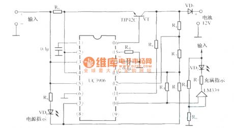
The circuit diagram of 12V sealed valve-regulated lead acid battery dual-level float charger UC3960
Published:2011/4/14 21:54:00 Author:muriel | Keyword: 12V , sealed valve-regulated, lead acid battery , dual-level float, charger
View full Circuit Diagram | Comments | Reading(1937)
DZW75-48/5050II equalized charge and floating charge change over circuit
Published:2011/4/14 1:21:00 Author:muriel | Keyword: equalized charge, floating charge, change over circuit

View full Circuit Diagram | Comments | Reading(482)
Multi-function remote control ceiling fan speed control circuit diagram
Published:2011/4/19 4:11:00 Author:Rebekka | Keyword: remote control ceiling fan, speed control circuit


This circuit consists of the following components.(1)It is composed of the CX20106 and the LC2200 infrared receiver and channel decoding circuit.(2)It is composed of preset down counter circuit, SCR trigger circuit and channel decoding circuit.(3)It is composed of the SCR trigger control VT5 and its base control resistor network composed of R13 ~ R16.
Applications required infrared transmitter circuit.
(View)
View full Circuit Diagram | Comments | Reading(4537)
Adjustable constant temperature controller circuit diagram
Published:2011/4/19 4:36:00 Author:Nicole | Keyword: constant temperature controller

The adjustable constant temperature controller circuit is asbelow. REF01E provides TMP17 with 10V high steady power supply, it can obtain a voltage singal from resistor R1, the voltage is in direct proportion t0 the measured temperature t. AD790 is a voltage comparator. If t represents the measured temperature and to represents the set value, when t>t0, the output of constant temperature controller is low level, when t<t0, it is high level. The value of to can be adjusted by potentiometer PR. C1 is denoising capacitance, C2 is accelerate capacitance. The output terminal of temperature control circuit controls the electric heating device by means of all kinds of actuators, then to achieve temperature control.
(View)
View full Circuit Diagram | Comments | Reading(728)
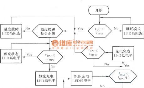
BQ2057 charging flow chart
Published:2011/4/14 1:20:00 Author:muriel | Keyword: charging flow chart
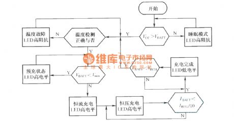
The BQ2057 typical charging characteristic curve:
(View)
View full Circuit Diagram | Comments | Reading(663)
The Changer circuit composed of BQ2000
Published:2011/4/18 4:29:00 Author:muriel | Keyword: Changer circuit
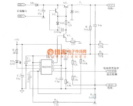
DCinput is 9-16V, VCC=5V, charge current is 1A, can charge four nickel-based batteries orone lithium ion battery; When R7 connect battery cathode. can chargefour nickel-based batteries;When R8 connect battery cathode, can charge one lithium ion battery. (View)
View full Circuit Diagram | Comments | Reading(1555)
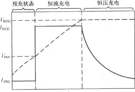
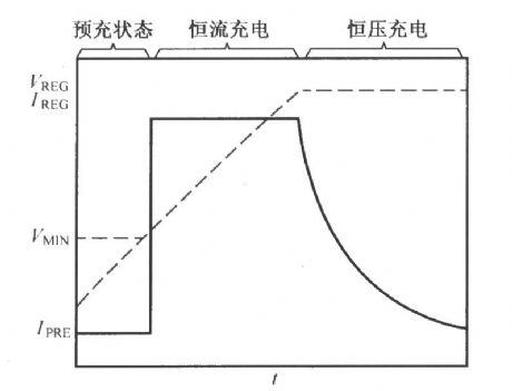
The charging process of BQ2057
Published:2011/4/14 1:13:00 Author:muriel | Keyword: charging process
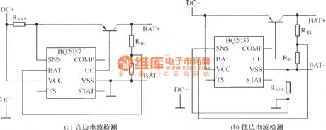
High and low current detection of constant current charging phase :
BQ2057 charging curve
(View)
View full Circuit Diagram | Comments | Reading(639)
Charger with BG602
Published:2011/4/14 1:11:00 Author:muriel | Keyword: charger

View full Circuit Diagram | Comments | Reading(441)
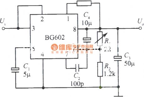
Low ripple wave integrated regulated power supply composed of BG602 1
Published:2011/4/14 5:59:00 Author:may | Keyword: Low ripple wave, integrated, regulated power supply
View full Circuit Diagram | Comments | Reading(507)
Negative output voltage integrated regulated power supply composed of BG602 2
Published:2011/4/14 1:11:00 Author:muriel | Keyword: Negative output voltage, integrated regulated power supply
View full Circuit Diagram | Comments | Reading(444)
900w full wave circuit
Published:2011/4/14 2:20:00 Author:muriel | Keyword: 900w, full wave circuit

The circuit is composed ofSingle junction transistor trigger bidirectional triode thyristor and bridge rectifier. It use theRT control a wide range of resistive load . Pulse transformer T isolates the single junction transistor steady-state current and silicon-controlled rectifier control extremely.
(View)
View full Circuit Diagram | Comments | Reading(885)
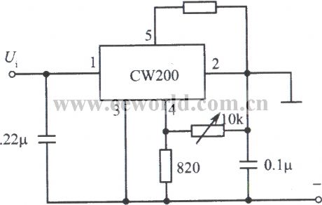
Slow start integrated regulated voltage power supply with CW200
Published:2011/3/30 2:08:00 Author:muriel | Keyword: slow start, integrated , regulated voltage power supply
View full Circuit Diagram | Comments | Reading(448)
Constant current source circuit with CW7900
Published:2011/3/30 2:08:00 Author:muriel | Keyword: constant current source circuit

View full Circuit Diagram | Comments | Reading(391)
Power amplitude modulator circuit with CW7900
Published:2011/3/30 2:07:00 Author:muriel | Keyword: power amplitude modulator

View full Circuit Diagram | Comments | Reading(479)
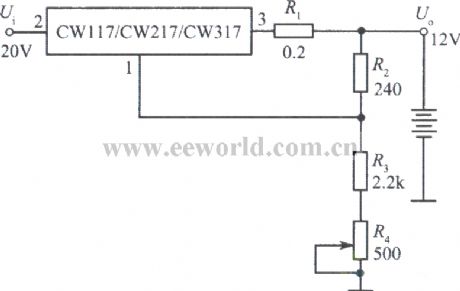
12V constant voltage charger with CW117
Published:2011/3/30 2:07:00 Author:muriel | Keyword: 12V , constant voltage, charger
View full Circuit Diagram | Comments | Reading(472)
Standard constant current source circuit with CW117
Published:2011/3/30 2:07:00 Author:muriel | Keyword: standard , constant current source circuit

View full Circuit Diagram | Comments | Reading(423)
| Pages:2060/2234 At 2020412042204320442045204620472048204920502051205220532054205520562057205820592060Under 20 |
Circuit Categories
power supply circuit
Amplifier Circuit
Basic Circuit
LED and Light Circuit
Sensor Circuit
Signal Processing
Electrical Equipment Circuit
Control Circuit
Remote Control Circuit
A/D-D/A Converter Circuit
Audio Circuit
Measuring and Test Circuit
Communication Circuit
Computer-Related Circuit
555 Circuit
Automotive Circuit
Repairing Circuit