Circuit Diagram
Index 2053
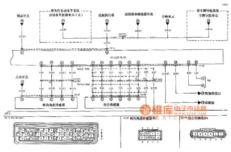
Shanghai General Buick LaCROSSE Car 3.0L Engine Circuit (5)
Published:2011/4/20 2:17:00 Author:Robert | Keyword: Shanghai General, Buick, LaCROSSE, 3.0L Engine
View full Circuit Diagram | Comments | Reading(375)
1kHz sine wave oscillator(741)
Published:2011/4/20 2:42:00 Author:Ecco | Keyword: 1kHz , sine wave, oscillator

The circuit shown in the chart is 1kHz sine wave oscillator circuit. Basing on the double-T circuit, the circuit using 741ordinary operational amplifier to produce 1000Hz sine wave output. Adjusting 100kΩ potentiometer will make circuit start oscillation, the oscillation frequency is determined by R1 and R2, and under normal circumstances, the value of two resistors is equal, the oscillation frequency is in inversely proportion with the resistance. Usually, the resistance is chosen between 4.7 ~ 18Ω, when the resistance of R1 and R2 is determined, the capacitor size could be selected according to need. In the figure, the resistor value choses 13Ω, capacitance is 0.01/μF.
(View)
View full Circuit Diagram | Comments | Reading(12039)
Shanghai General Buick LaCROSSE Car 3.0L Engine Circuit (6)
Published:2011/4/20 2:16:00 Author:Robert | Keyword: Shanghai General, Buick, LaCROSSE, 3.0L Engine
View full Circuit Diagram | Comments | Reading(411)
Shanghai General Buick LaCROSSE Car 3.0L Engine Circuit (7)
Published:2011/4/20 2:16:00 Author:Robert | Keyword: Shanghai General, Buick, LaCROSSE, 3.0L Engine
View full Circuit Diagram | Comments | Reading(396)
Shanghai General Buick LaCROSSE Car 3.0L Engine Circuit (8)
Published:2011/4/20 2:16:00 Author:Robert | Keyword: Shanghai General, Buick, LaCROSSE, 3.0L Engine
View full Circuit Diagram | Comments | Reading(519)
Shanghai General Buick LaCROSSE Car 3.0L Engine Circuit (9)
Published:2011/4/20 2:16:00 Author:Robert | Keyword: Shanghai General, Buick, LaCROSSE, 3.0L Engine
View full Circuit Diagram | Comments | Reading(348)
Shanghai General Buick LaCROSSE Car 3.0L Engine Circuit (10)
Published:2011/4/20 2:15:00 Author:Robert | Keyword: Shanghai General, Buick, LaCROSSE, 3.0L Engine
View full Circuit Diagram | Comments | Reading(326)
Shanghai General Buick LaCROSSE Car 3.0L Engine Circuit (11)
Published:2011/4/20 2:15:00 Author:Robert | Keyword: Shanghai General, Buick, LaCROSSE, 3.0L Engine
View full Circuit Diagram | Comments | Reading(390)
Saima car ignition system circuit
Published:2011/4/20 2:45:00 Author:Jessie | Keyword: car ignition system
View full Circuit Diagram | Comments | Reading(386)
Ultrasonic remote control dimming light receiver
Published:2011/4/20 1:30:00 Author:Nicole | Keyword: ultrasonic remote control, dimming light


Ultrasonic transmitter circuit:
Ultrasonic remote control dimming receiver circuit:
B1、B2 adopt well-assorted TCT40-12F2 and TCT40-12F2 piezoelectric ceramics ultrasonic transducer. (View)
View full Circuit Diagram | Comments | Reading(1862)
Paliao ABS circuit
Published:2011/4/20 2:44:00 Author:Jessie | Keyword: ABS
View full Circuit Diagram | Comments | Reading(887)
Night automatic light circuit with TRIAC
Published:2011/4/20 2:39:00 Author:Nicole | Keyword: automatic light, TRIAC

The circuit is as shown, it adopts phototransistor as illuminance sensor. In daytime with high illuminance, the phototransistor L14C1 turns on. Diode VD3 turns on too, then the pressure drop on capacitor C2 is zero, bidirectional trigger VD5 and TRIAC VT are all off, the light is not on. On the contrary, at night L14C1 turns off, C2 has voltage to make ST4 and VT turn on, the light will light automatically. (View)
View full Circuit Diagram | Comments | Reading(1259)
Shanghai General Buick LaCROSSE Car 3.0L Engine Circuit (12)
Published:2011/4/20 2:15:00 Author:Robert | Keyword: Shanghai General, Buick, LaCROSSE, 3.0L Engine
View full Circuit Diagram | Comments | Reading(394)
Shanghai General Buick LaCROSSE Car 2.4L Engine Circuit (1)
Published:2011/4/20 2:14:00 Author:Robert | Keyword: Shanghai General, Buick, LaCROSSE, 2.4L Engine
View full Circuit Diagram | Comments | Reading(406)
Shanghai General Buick LaCROSSE Car 2.4L Engine Circuit (2)
Published:2011/4/20 2:14:00 Author:Robert | Keyword: Shanghai General, Buick, LaCROSSE, 2.4L Engine
View full Circuit Diagram | Comments | Reading(423)
The motor vehicle headlight auto-dimming controller 9
Published:2011/4/19 21:54:00 Author:Ecco | Keyword: motor vehicle , headlight, auto-dimming , controller

The working principle.The vehicle headlight auto-dimming controller circuit consists of phototransistor Vl, transistors V2 and V3, resistor Rl-R5, capacitor C, diode VD and relay K, the circuit is shown as the figure 7-9.
S is headlamp switch of car, EL2 is the internallow beam light of headlamp, ELlis the high beam. V2 and V3forms a Schmitt trigger circuit.
When driving at night, turning on S, + l2V voltage is added to the high beam by the normally closed contact of S and K, so that the EL2 islit.
When meeting other cars, the light exposure from the opposite traveling car will make the conduction ability of V1and V2 increase, V3 turns on, K gets power and pulls in, the normally open contact isconnected, high beam ELl turns off,low beamEL2 turns on.
After meeting cars, the internal resistance of V1 will increaseas it has no light exposure,the conduction ability of V2 decreases, V3 is cut off, K releases, the normally closed contact is connected, normally open contact is disconnected, ELl turns on,low beamEL2 turns off.
C is a positive feedback circuit, which makes Schmitt trigger circuit delay.
R1-R5 choose 1/4W metal film resistors or carbon film resistors.
C chooses monolithic capacitors or polyester capacitor.
VD uses lN4007 silicon rectifier diode.
K selects a l2V 4098 DC relay.
(View)
View full Circuit Diagram | Comments | Reading(1367)
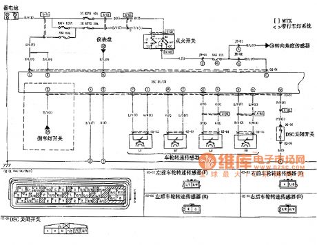
M6 car DSC system circuit
Published:2011/4/20 2:38:00 Author:Jessie | Keyword: DSC system
View full Circuit Diagram | Comments | Reading(747)
Shanghai General Buick LaCROSSE Car 2.4L Engine Circuit (4)
Published:2011/4/20 2:14:00 Author:Robert | Keyword: Shanghai General, Buick, LaCROSSE, 2.4L Engine
View full Circuit Diagram | Comments | Reading(401)
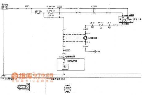
M6 car AC compressor control circuit
Published:2011/4/20 2:35:00 Author:Jessie | Keyword: AC compressor control
View full Circuit Diagram | Comments | Reading(1079)
The motor vehicle headlight auto-dimming controller
Published:2011/4/19 21:04:00 Author:Ecco | Keyword: motor vehicle, headlight , auto-dimming , controller

The working principle.
The vehicle headlight auto-dimming controller circuit consists of photoresistor RG, potentiometer Rp, transistor V, diode VD and relay K, the circuit is shown as the figure 7-8.
When driving at night, turning on the headlamp switch S, RG is in the high impedance state when no light exposure, V cuts off, K isin releasing state, the normally closed contact Kl is connected, the normally open contact K2 is off, the internal high beam ELl of headlamp is lit, low beam EL2 is off.
When meeting other cars at night, the internal resistance of RC will decrease as the light exposure from the opposite traveling car, V will be saturated and conducted, K gets power and pulls in, the normally closed contact is disconnected, normally open contact is connected, the high beam ELl turns off, the low beam EHL2 turns on, that realizes the auto-dimming control. After meeting other cars, RG is in high impedance state, V cuts off, K releases, and the headlight automatically restores the upper light state.
RG usesMG45 seriesphotosensitive resistor.
RP uses small multi-turn potentiometers or variable resistor with carbon film synthesis.
VD uses lN4007 silicon rectifier diode.
V uses S8550 PNP transistors.
K selects a l2V JRX-l3F or JQX-4 DC relay.
(View)
View full Circuit Diagram | Comments | Reading(1540)
| Pages:2053/2234 At 2020412042204320442045204620472048204920502051205220532054205520562057205820592060Under 20 |
Circuit Categories
power supply circuit
Amplifier Circuit
Basic Circuit
LED and Light Circuit
Sensor Circuit
Signal Processing
Electrical Equipment Circuit
Control Circuit
Remote Control Circuit
A/D-D/A Converter Circuit
Audio Circuit
Measuring and Test Circuit
Communication Circuit
Computer-Related Circuit
555 Circuit
Automotive Circuit
Repairing Circuit


