
Circuit Diagram
Index 2046
74 series digital circuit of 7482 2-bit binary full adder
Published:2011/4/5 22:52:00 Author:Ecco | Keyword: digital circuit , 2-bit binary, full adder
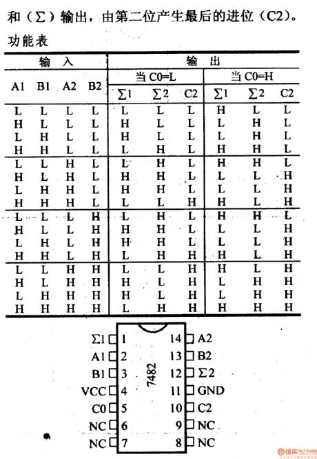

∑ output, and carry bit is produced by the second bit.
7482 2-bit binary full adder: To execute 2-bit binary addition. (View)
View full Circuit Diagram | Comments | Reading(3035)
74 series digital circuit of 74H87 binary true form/inverse code and O/I circuit
Published:2011/4/2 4:09:00 Author:Ecco | Keyword: digital circuit , binary true form, Anti-code , O/I circuit


74H87 binary true form/Anti-code, O/I circuit (View)
View full Circuit Diagram | Comments | Reading(712)
Automatic gas circulatory stove temperature control circuit diagram
Published:2011/4/14 2:22:00 Author:Ecco | Keyword: Automatic , gas circulatory stove, temperature control

1. Manual method: First, to pull combination switch HK to manual position, then the contacts of KK1 are connected, the relay J coil is energized pull, the AC contactor IC takes action, resistance furnaceis heating, when the temperature rose to the required temperature, to pull KK to 0 position, so that J and JC coil lose power, electrical furnace loses the power, and it won's rise the temperature again.
2. Automatic way: To pull combination switch HK to the automatic position, then the contacts of KK2 are connected, since the digital potentiometer thermometer CB is below the predetermined temperature, contact CB is closed, so that J is energized pull, and IC coils get electric power to heat up the electrical furnace. When the temperature reaches a predetermined temperature, contact CB automatic breaking, so that J coil and IC breaking, electrical furnace stops heating, to realize automatic temperature control.
The K in the chart is the power switch of meter. HD and LD are the energizing and breaking indications.
(View)
View full Circuit Diagram | Comments | Reading(549)
TWL2213 typical application circuit charge circuit
Published:2011/4/20 8:08:00 Author:Nicole | Keyword: typical application, charge
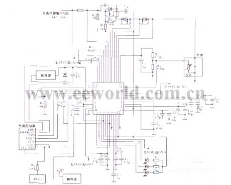
The related components information applied in this circuit: TWL2213 is mainly used in power management of portable instruments or equipments which is powered by lithium ion battery such as PAD, telephone, pager. It is also designed for charging to lithium ion battery. The typical circuit is as below:
(View)
View full Circuit Diagram | Comments | Reading(564)
Astable Multivibrator Circuit
Published:2011/4/20 20:43:00 Author:Sue | Keyword: Astable, Multivibrator

View full Circuit Diagram | Comments | Reading(927)
TWL2213 pin arrangement diagram
Published:2011/4/20 7:52:00 Author:Nicole | Keyword: pin
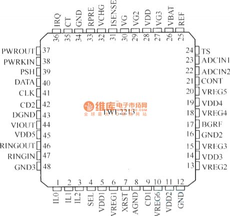
TWL2213 is produced by US TI Company, it is a new type power management and lithium ion battery charge control IC, it is designed for portable IT products. (View)
View full Circuit Diagram | Comments | Reading(530)
Voltage monitoring and reset circuit with TL7705CP
Published:2011/4/20 4:38:00 Author:Nicole | Keyword: Voltage monitoring, reset

View full Circuit Diagram | Comments | Reading(541)
TIL probe circuit
Published:2011/4/20 8:55:00 Author:Nicole | Keyword: probe

If the polarity switch is in the position as shown, when the input probe receives low level(nagative)pulse, LED lights and it will keep lighting until the circuit is reset. If the switch is put to another position, when there is high level or +5V input pulse, LED lights too. (View)
View full Circuit Diagram | Comments | Reading(529)
The multivibrator composed of D flip-flop
Published:2011/4/14 2:38:00 Author:Ecco | Keyword: multivibrator , D flip-flop
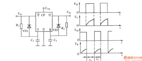
T0 connect theQ output terminal of D flip-flopto RC components toform a monostable trigger. The non-output terminal of Q connects to a group of RC components, they will make up a non-steady-state circuit, and it's a multivibrator. The composition is shown as the chart:
(View)
View full Circuit Diagram | Comments | Reading(1362)
1kHz Audio square wave generator
Published:2011/4/20 5:50:00 Author:Ecco | Keyword: 1kHz, Audio , square wave, generator
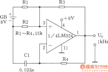
The lkHz left and right audio square wave generator is mainly composed of the comparator LM324 and R2, R3, R4 and Cl, the circuit is shown as the chart. The reference voltage GB / 2 on input end of pin 3 of LM324 is got by the voltage divider circuit Rl, R2. The R2 and R3 constitute positive feedback, integral circuit R4 and Cl constitute negative feedback. First taking the value of R2 and R3 make R2 / (R2 + R3) = 0.5, then the square wave repetition frequency f = 1/2R4 · Cl, if selecting Cl = 0.033pF, R4 = 15kΩ, the substituted f = lkHz. Changing Cl or R4 can change the oscillation frequency.
(View)
View full Circuit Diagram | Comments | Reading(2571)
Photoelectric isolation circuit between TTL circuit and relay circuit
Published:2011/4/20 8:44:00 Author:Nicole | Keyword: photoelectric isolation, TTL, relay

In this circuit, using a photoelectric coupler can reach 100GΩ isolation between TTL and relay circuit, it avoids relay noise and peak voltage influencing TTL circuit.
When the TTL input singal is high, Q1 turns on, there is no current in LED, and there is no light incident on detecor, photoelectric diode is in 5GΩ maximum impedance value. So Q2 is nonconductive, then Q3 is nonconductive too, and there is no current in relay coil. (View)
View full Circuit Diagram | Comments | Reading(1349)
M62253FP charge controllor
Published:2011/4/20 9:01:00 Author:Nicole | Keyword: charge controller


M62253FP is produced by Janpan Mitsubishi Electric C.Ltd, it is used specifically for the charge controllor of lithium ion battery. The pin arrangement diagram is as below:
(View)
View full Circuit Diagram | Comments | Reading(383)
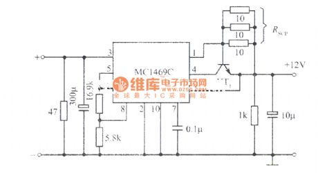
High stable 12V regulated power supply composed of MC1469C integrated regulator
Published:2011/4/20 4:42:00 Author:Nicole | Keyword: 12V regulated power supply, integrated regulator
View full Circuit Diagram | Comments | Reading(697)
Greenhouse or plastic house anti-condensation automatic vent with birdsong phonation circuit
Published:2011/4/20 6:43:00 Author:Nicole | Keyword: greenhouse, plastic house, automatic vent, birdsong

The circuit is as shown. It is composed of resistor type dew condensation sensor, electronic switch, relay control discharge fan circuit, birdsong phonation circuit, audio power amplifier circuit and AC depressurization rectifier circuit. RH is a resistor type dew condensation sensor, it is sensitive to the high humidity air, and it can detect whether the steam in the air will be dew condensation. (View)
View full Circuit Diagram | Comments | Reading(1071)
Greenhouse flower seedling humidity control with birdsong circuit
Published:2011/4/20 20:18:00 Author:Nicole | Keyword: greenhouse, flower seedling, birdsong

The circuit is as shown, it is composed of humidity semsor, detection circuit, temperature indicator, comparison circuit, SCR control heating circuit, birdsong phonation circuit and AC depressurization rectifier circuit. RH is humidity sensor, it adopts MS01-B, when the relative humidity changes in the range of 20%~90%, its resistance will change between few KΩ and several hundreds kΩ. (View)
View full Circuit Diagram | Comments | Reading(1033)
Vegetable greenhouse humidity detection automatic ventilating with cricket chirped circuit
Published:2011/4/20 4:31:00 Author:Nicole | Keyword: vegetable greenhouse, humidity detection, automatic ventilating, cricket chirped

The circuit is as shown. It consists of temperature detection circuit, schmidt trigger circuit, SCR control ventilating circuit, voice phonation circuit and AC depressurization rectifier circuit. It can detect the high humidity environment, when the relative humidity beyond the set value, the circuit will send out cricket chirp, and start discharge fan to operate, ventilate. (View)
View full Circuit Diagram | Comments | Reading(739)
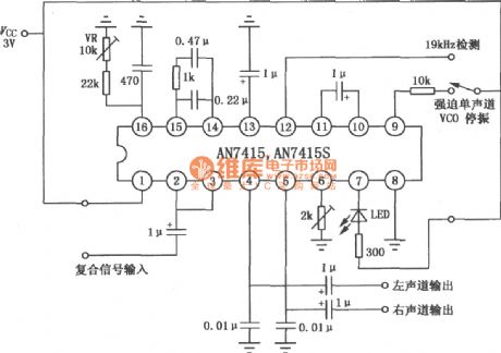
Circuit Of AN7415/7415S FM Stereo Decoder
Published:2011/4/20 8:13:00 Author:TaoXi | Keyword: FM, Stereo Decoder
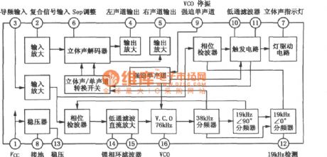
The Internal Block Diagram of The AN7415/7415S
 The Typical Application Circuit Of The AN7415/7415S (View)
View full Circuit Diagram | Comments | Reading(2547)
Circuit Of Induction Telephone Loudspeaker
Published:2011/4/20 9:36:00 Author:TaoXi | Keyword: Induction, Telephone Loudspeaker
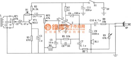
In some cases such as the telephone conference, we need to amplify the voice of telephone to lots of people, and we need to record the contents from the telephone. This circuit can simultaneously satisfy both of these requirements, do not need to make any changes, just put it near the telephone. When the voice current through the coil inside the telephone, there is a magnetic field in the vicinity, so If you put a coil L at both ends, the magnetic field will induce the signal voltage, then amplify the signal to amplify the voice of telephone to lots of people. Telephone inductive amplifier circuit is as shown, coil L will be converted the leakage magnetic field of voice into the electric signal, then controlled by potentiometer RP1 to get into the pre-formed amplifier stage that is composed by the transistor VT1, through the capacitor C4 and the potentiometer RP2 to get into the power amplifier stage to be amplified by the IC1 (audio integrated amplifier LM2896), output signal of pin IC1 promote sound speaker BL1 to make sound.
(View)
View full Circuit Diagram | Comments | Reading(1701)
Circuit Of LAG665D/665F Single Cassette Stereo Player
Published:2011/4/20 8:06:00 Author:TaoXi | Keyword: Single Cassette, Stereo
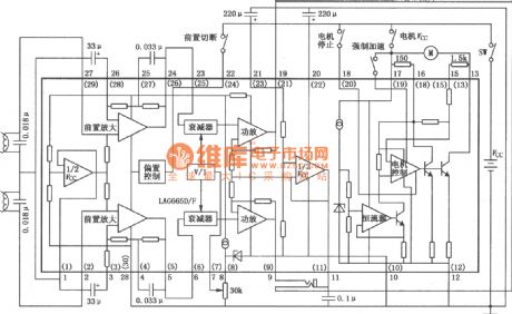
The Circuit Of LAG665D/665F Single Cassette Stereo Player is as shown. (View)
View full Circuit Diagram | Comments | Reading(733)
Neighbor Pulse Delay Circuit(555)
Published:2011/4/20 19:48:00 Author:Sue | Keyword: Neighbor, Pulse, Delay, 555

View full Circuit Diagram | Comments | Reading(1472)
| Pages:2046/2234 At 2020412042204320442045204620472048204920502051205220532054205520562057205820592060Under 20 |
Circuit Categories
power supply circuit
Amplifier Circuit
Basic Circuit
LED and Light Circuit
Sensor Circuit
Signal Processing
Electrical Equipment Circuit
Control Circuit
Remote Control Circuit
A/D-D/A Converter Circuit
Audio Circuit
Measuring and Test Circuit
Communication Circuit
Computer-Related Circuit
555 Circuit
Automotive Circuit
Repairing Circuit