Circuit Diagram
Index 2044
SHANGHAI GM Chevrolet(Epica)saloon car instrument board circuit diagram(six)
Published:2011/4/20 20:21:00 Author:muriel | Keyword: SHANGHAI GM Chevrolet(Epica), saloon car, instrument board

SHANGHAI GM Chevrolet(Epica)saloon car instrument board circuit diagram(six)
(View)
View full Circuit Diagram | Comments | Reading(416)
SHANGHAI GM Chevrolet(Epica)saloon car instrument board circuit diagram(seven)
Published:2011/4/20 20:20:00 Author:muriel | Keyword: SHANGHAI GM Chevrolet(Epica), saloon car , instrument board

SHANGHAI GM Chevrolet(Epica)saloon car instrument board circuit diagram(seven)
(View)
View full Circuit Diagram | Comments | Reading(267)
SHANGHAI GM Chevrolet(Epica)saloon car instrument board circuit diagram(eight)
Published:2011/4/20 20:20:00 Author:muriel | Keyword: SHANGHAI GM Chevrolet(Epica), saloon car , instrument board

SHANGHAI GM Chevrolet(Epica)saloon car instrument board circuit diagram(eight)
(View)
View full Circuit Diagram | Comments | Reading(273)
SHANGHAI GM Chevrolet(Epica)saloon car anti-theft system circuit diagram(one)
Published:2011/4/20 20:15:00 Author:muriel | Keyword: SHANGHAI GM Chevrolet(Epica), saloon car , anti-theft system

SHANGHAI GM Chevrolet(Epica)saloon car anti-theft system circuit diagram(one)
(View)
View full Circuit Diagram | Comments | Reading(431)
SHANGHAI GM Chevrolet(Epica)saloon car anti-theft system circuit diagram(two)
Published:2011/4/20 20:14:00 Author:muriel | Keyword: SHANGHAI GM Chevrolet(Epica), saloon car, anti-theft system

SHANGHAI GM Chevrolet(Epica)saloon car anti-theft system circuit diagram(two)
(View)
View full Circuit Diagram | Comments | Reading(370)
SHANGHAI GM BUICK(Royaum)saloon car vehicle control module circuit diagram(one)
Published:2011/4/20 20:32:00 Author:muriel | Keyword: SHANGHAI GM BUICK(Royaum), saloon car , vehicle control module

Figure SHANGHAI GM BUICK(Royaum)saloon car vehicle control module circuit diagram(one)--ignition key, receiving sensor, public power supply and earthing (View)
View full Circuit Diagram | Comments | Reading(1187)
555 Fans Electronic Timer Circuit
Published:2011/4/20 10:01:00 Author:Robert | Keyword: Fans, Electronic Timer

555 Fans Electronic Timer Circuit as shown below:
(View)
View full Circuit Diagram | Comments | Reading(719)
SHANGHAI GM Chevrolet(Epica)saloon car instrument board circuit diagram(four)
Published:2011/4/20 20:22:00 Author:muriel | Keyword: SHANGHAI GM Chevrolet(Epica), saloon car, instrument board

SHANGHAI GM Chevrolet(Epica)saloon car instrument board circuit diagram(four)
(View)
View full Circuit Diagram | Comments | Reading(314)
Electronic Chameleon Circuit
Published:2011/4/20 10:15:00 Author:Robert | Keyword: Electronic Chameleon

Electronic Chameleon Circuit as shown below:
Welcome to reprint, information come from Weiku Electric Market Website (www.seekic.com) (View)
View full Circuit Diagram | Comments | Reading(1003)
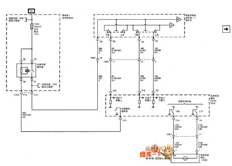
SHANGHAI GM Chevrolet(Epica)saloon car rearview mirror/car window circuit diagram(one)
Published:2011/4/20 20:13:00 Author:muriel | Keyword: SHANGHAI GM Chevrolet(Epica), saloon car, rearview mirror, car window

SHANGHAI GM Chevrolet(Epica)saloon car rearview mirror/car window circuit diagram(one)
(View)
View full Circuit Diagram | Comments | Reading(547)
SHANGHAI GM Chevrolet(Epica)saloon car rearview mirror/car window circuit diagram(two)
Published:2011/4/20 20:13:00 Author:muriel | Keyword: SHANGHAI GM Chevrolet(Epica), saloon car, rearview mirror, car window

SHANGHAI GM Chevrolet(Epica)saloon car rearview mirror/car window circuit diagram(two)
(View)
View full Circuit Diagram | Comments | Reading(381)
555 Electric Fan Multi-function Timer Control Circuit
Published:2011/4/20 8:19:00 Author:Robert | Keyword: 555, Electric Fan, Multi-function Timer

555 Electric Fan Multi-function Timer Control Circuit as shown below.
(View)
View full Circuit Diagram | Comments | Reading(1014)
Circuit Of KA2213 Single Tape Recorder
Published:2011/4/20 7:21:00 Author:TaoXi | Keyword: KA2213, Single Tape, Recorder

The circuit of KA2213 single tape recorder is as shown. (View)
View full Circuit Diagram | Comments | Reading(2445)
Novel neon-electroscope circuit
Published:2011/4/13 4:21:00 Author:Nicole | Keyword: neon-electroscope

When measuring municipal electric power, the weak current flowsresistance and neon tube, making the neon tube luminescence, and the oscillation circuit composed of CMOS IC starts to oscillate, piezoceramics produces a sound. (View)
View full Circuit Diagram | Comments | Reading(1037)
Serial voltage stabilizing circuit with few residual Voltage
Published:2011/4/13 4:13:00 Author:Nicole | Keyword: voltage stabilizing, few residual voltage

This circuit uses the collector of serial transistor as output terminal, the minimum voltage difference between lowest roll in voltage and steady output voltage can reach 1.2V. Adopting two regulator tubes can ensure the output voltage with high stability. Using 2.5kΩ potentiometer can set output voltage to the given value. 1nF capacitance can suppress high frequency oscillation. (View)
View full Circuit Diagram | Comments | Reading(508)
Larger current steady voltage circuit with current limit
Published:2011/4/17 8:07:00 Author:Nicole | Keyword: larger current, steady voltage, current limit

In figure, the choice of resistances R1 and R2 should meet the condition of R2≧5*R1. Such as R1=0.2Ω, R2=1Ω. In practice, according to the current, R1 should be between 0.1~2Ω, because of UBE=UD, then UR1=UR2, so I2 is lower than 5 times of I3, total current I1=I2+I3≈I4, neglecting the base current of transistor, then I3 is equal to the adjustment current of integrated circuit IC. For large current transistor, the resistance R3 can be selected between 10~20Ω. For small current transistor, the resistance can be choiced of 100Ω. (View)
View full Circuit Diagram | Comments | Reading(498)
Pulse Signal Generator(74LS10、74LS00) Circuit
Published:2011/4/20 20:44:00 Author:Sue | Keyword: Pulse, Signal Generator
View full Circuit Diagram | Comments | Reading(1406)
Circuit of Simplified Pulse Generator with Adjustable Duty Ratio
Published:2011/4/20 20:44:00 Author:Sue | Keyword: Simplified, Adjustable Duty, Pulse, Generator

As seen here is t (View)
View full Circuit Diagram | Comments | Reading(387)
A kind of full automatic charger circuit
Published:2011/4/19 4:25:00 Author:May | Keyword: full automatic charger
working principleDiagram 4-27 is the principle diagram of this charger. The voltage of LM339's pin 5 V5=6V. When the battery voltage E is less than 12V, V4 is less than 6V. LM339's pin 2 outputs high level. It can let 9013 saturation. 3AD30 is on amplified state. The measured value is 300mA when using heavy current to charge. When E≥12V, V5≥6V. LM339's pin 2 output low level. 9013 and 3AD30 is cut off. It adopts 40mA low current to charge to the battery. The curved line of measured charge current is shown in diagram 4-28.
(View)
View full Circuit Diagram | Comments | Reading(1646)
Hisense TC2102GD TV switching power supply (MC44608P75) circuit diagram
Published:2011/4/20 9:06:00 Author:Nicole | Keyword: Hisense, TV Power Supply
View full Circuit Diagram | Comments | Reading(3157)
| Pages:2044/2234 At 2020412042204320442045204620472048204920502051205220532054205520562057205820592060Under 20 |
Circuit Categories
power supply circuit
Amplifier Circuit
Basic Circuit
LED and Light Circuit
Sensor Circuit
Signal Processing
Electrical Equipment Circuit
Control Circuit
Remote Control Circuit
A/D-D/A Converter Circuit
Audio Circuit
Measuring and Test Circuit
Communication Circuit
Computer-Related Circuit
555 Circuit
Automotive Circuit
Repairing Circuit

