
Circuit Diagram
Index 2078
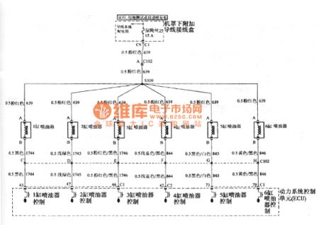
Buick GL8 injector circuit
Published:2011/4/18 4:33:00 Author:Jessie | Keyword: injector
View full Circuit Diagram | Comments | Reading(371)
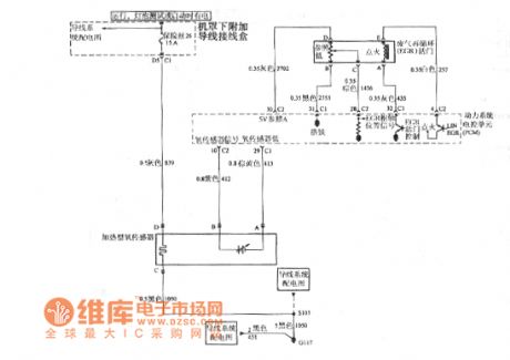
Buick GL8 oxygen sensors, waste gas recirculation and power systems control unit circuit
Published:2011/4/18 4:32:00 Author:Jessie | Keyword: oxygen sensors, waste gas recirculation, power systems, control unit
View full Circuit Diagram | Comments | Reading(414)
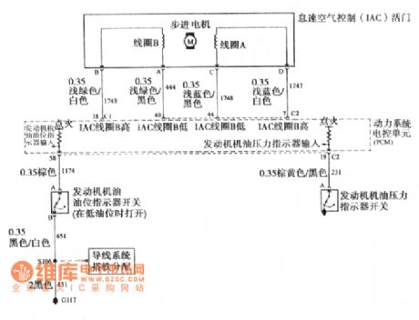
Buick GL8 idle speed control, oil level switches and oil pressure indicator light circuit
Published:2011/4/18 4:34:00 Author:Jessie | Keyword: idle speed control, oil level switches, oil pressure indicator light
View full Circuit Diagram | Comments | Reading(485)
Isolation RTD temperature amplifying circuit with ISO106
Published:2011/4/18 4:36:00 Author:Jessie

View full Circuit Diagram | Comments | Reading(479)
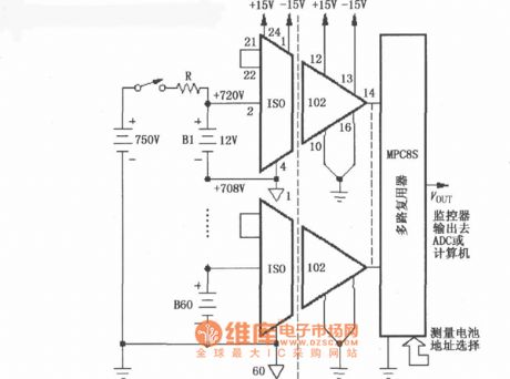
The battery monitoring circuit in the high-voltage charging circuit with ISO102
Published:2011/4/18 4:38:00 Author:Jessie | Keyword: The battery monitoring, high-voltage charging
View full Circuit Diagram | Comments | Reading(423)
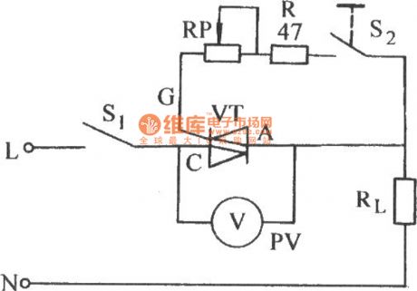
Bi-directional thyristor gate limit flow resistance regulating circuit
Published:2011/4/18 4:30:00 Author:Jessie | Keyword: Bi-directional thyristor, gate limit flow, resistance, regulating
View full Circuit Diagram | Comments | Reading(555)
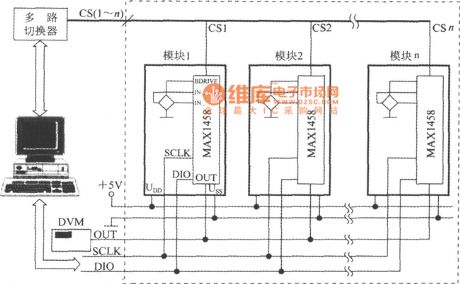
Pressure test circuit with digital pressure signal disposal device MAX1458
Published:2011/4/18 2:31:00 Author:Jessie | Keyword: Pressure test, digital pressure signal disposal device
View full Circuit Diagram | Comments | Reading(356)
4~20mA Isolation analog (ISO100) circuit
Published:2011/4/18 4:27:00 Author:Jessie | Keyword: Isolation analog

View full Circuit Diagram | Comments | Reading(720)
4302 Division circuit
Published:2011/4/14 20:35:00 Author:Jessie | Keyword: 4302 Division

As shownis the division circuit composed by integrated block 4302, the inputs are V1 and V2, its output Vo is: Vo=10V1/V2. The input signal range: 0.03V≤V1≤10V, 0.03V≤V2≤10V. The circuit's typical error is ±25mV at 25℃, the max error is ±50mV, and output voltage accuracy affected by temperature, its temperature coefficient is ±1mV/C, output disorders voltage is 士10mV at 25℃, temperature coefficient is ±lmV/C. V1, V2's bandwidth in small signal is 500 kHzin small signal (-3dB), full range output is 60kHz. The adjustment method ofR1, R2 and R3 is: when V1=V2=+10V, adjust R1 to make the output Vo = +10V; When Vl=V2=+0.1V, adjust R2 to make output Vo=+10V; When V1=+0.01V, V2=+0.1V, adjust R3 to make Vo=+1V. So can adjust again and againfor a few times. (View)
View full Circuit Diagram | Comments | Reading(549)
Pyroelectric infrared sensor induction control circuit 1
Published:2011/4/12 3:41:00 Author:Jessie | Keyword: Pyroelectric infrared, sensor induction control
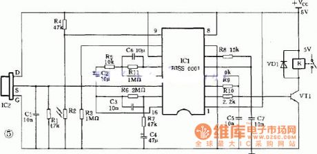
This type of control circuit mainly consists of pyroelectric infrared sensor and amplifying circuit. Pyroelectric infrared sensor isa new type of sensitive components, it is made from high thermoelectric coefficient materialswith impedance matching mosfet and filter piece. Pyroelectric infrared sensor is able to detect infrared ray radiation human issued in contactless manner, and translate it into electrical signal to send out.
(View)
View full Circuit Diagram | Comments | Reading(1660)
The current control circuit using discrete transistor
Published:2011/4/12 3:38:00 Author:Jessie | Keyword: discrete transistor, current control

View full Circuit Diagram | Comments | Reading(629)
Insulation DC voltage detected circuit diagram
Published:2011/4/12 3:37:00 Author:Jessie | Keyword: Insulation DC voltage detected

View full Circuit Diagram | Comments | Reading(308)
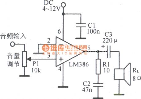
LM386 typical applications circuit
Published:2011/4/12 3:37:00 Author:Jessie | Keyword: typical applications
View full Circuit Diagram | Comments | Reading(1300)
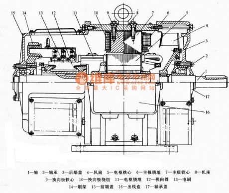
Small and medium-sized DC motor structure diagram
Published:2011/4/11 23:02:00 Author:Jessie | Keyword: Small and medium-sized, DC motor structure
View full Circuit Diagram | Comments | Reading(1345)
Simple combustible gas alarm circuit
Published:2011/4/11 23:54:00 Author:Jessie | Keyword: Simple, combustible gas, alarm

View full Circuit Diagram | Comments | Reading(550)
Sanhe Songshi 15W vibrating massage stick circuit
Published:2011/4/18 2:58:00 Author:Ecco | Keyword: Sanhe , Songshi , 15W , vibrating, massage stick

View full Circuit Diagram | Comments | Reading(1168)
Sine wave generator composed of inverter
Published:2011/4/18 2:27:00 Author:Ecco | Keyword: Sine wave generator , inverter

The sine wave generator composed of inverter is shown as the chart. The circuit could get high stable sine wave in more than a few MHz. In the figure, A1 and the crystal oscillator form a oscillating circuit, the output of A1 becomes sine wave signal after passing the buffer A2. In the circuit, A1 is linear amplifier, the whole circuit is in amplifying state. As the characteristics of the crystal oscillator are different, the output frequency and voltage are different, and R2 is used to adjust waveform. For getting ccurate oscillation frequency, it can connect a variable capacitor on two ports of capacitor C1 in parallel. Oscillation frequency of the circuit is decided by crystal oscillator, it can change the output signal frequency.
(View)
View full Circuit Diagram | Comments | Reading(2041)
CMOS 555 equivalent function circuit diagram
Published:2011/4/18 4:39:00 Author:Ecco | Keyword: CMOS , 555 , equivalent function

View full Circuit Diagram | Comments | Reading(734)
Haier M0-2270M1/M0-2270M2 microwave circuit
Published:2011/4/18 2:46:00 Author:Ecco | Keyword: Haier , microwave

Haier M0-2270M1/M0-2270M2 microwave circuit. Note: The circuit is in the state when the door is open and the timer is not working.
(View)
View full Circuit Diagram | Comments | Reading(606)
Double digital display amblyopia therapeutic apparatus for children
Published:2011/4/18 2:54:00 Author:Ecco | Keyword: Double digital display, amblyopia , therapeutic apparatus , children
Double digital display amblyopia therapeutic apparatus circuit for children is as below: (a) is the whole circuit; (b) is the counter circuit.
(View)
View full Circuit Diagram | Comments | Reading(514)
| Pages:2078/2234 At 2020612062206320642065206620672068206920702071207220732074207520762077207820792080Under 20 |
Circuit Categories
power supply circuit
Amplifier Circuit
Basic Circuit
LED and Light Circuit
Sensor Circuit
Signal Processing
Electrical Equipment Circuit
Control Circuit
Remote Control Circuit
A/D-D/A Converter Circuit
Audio Circuit
Measuring and Test Circuit
Communication Circuit
Computer-Related Circuit
555 Circuit
Automotive Circuit
Repairing Circuit