
Circuit Diagram
Index 2070
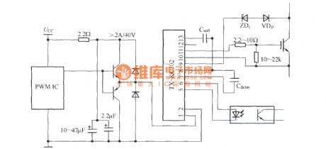
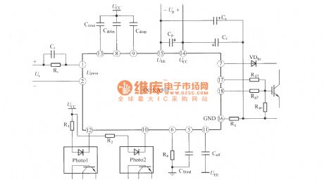
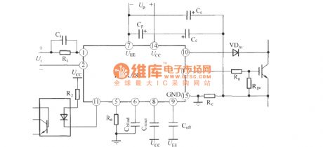
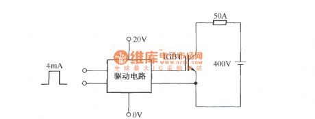
TX—KCl02 application cording diagram
Published:2011/4/8 0:44:00 Author:muriel | Keyword: application cording diagram
View full Circuit Diagram | Comments | Reading(427)
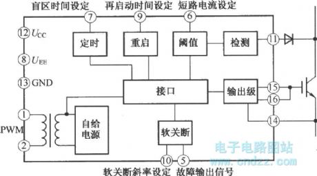
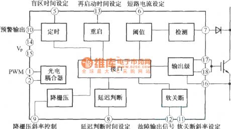
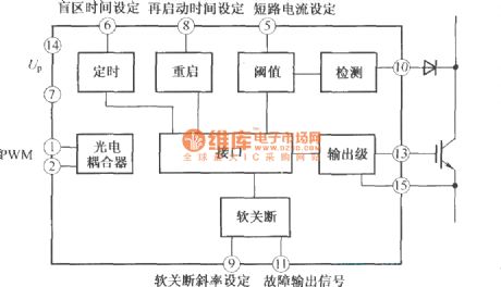
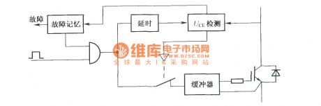
TX-KCl02IGBT driver functional block diagram
Published:2011/4/8 0:44:00 Author:muriel | Keyword: driver, functional block diagram
View full Circuit Diagram | Comments | Reading(454)
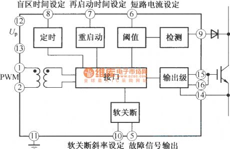
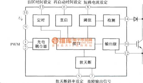
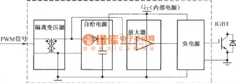
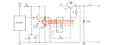
TX-KBl02 functional block diagram
Published:2011/4/8 0:43:00 Author:muriel | Keyword: functional block diagram
View full Circuit Diagram | Comments | Reading(477)
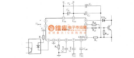
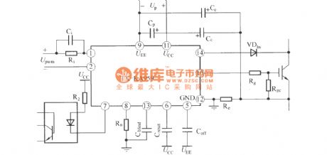
TX-KBl02 application wiring scheme
Published:2011/4/8 0:41:00 Author:muriel | Keyword: application wiring scheme
View full Circuit Diagram | Comments | Reading(439)
TX—KAl01 IGBT driver functional block diagram
Published:2011/4/8 0:40:00 Author:muriel | Keyword: IGBT driver, functional block diagram
View full Circuit Diagram | Comments | Reading(666)
TX-KAl01(IGBT driver) application wiring scheme
Published:2011/4/8 0:41:00 Author:muriel | Keyword: application wiring scheme, IGBT driver
View full Circuit Diagram | Comments | Reading(1206)
TX-KA959 IGBT driver functional block diagram
Published:2011/4/8 0:40:00 Author:muriel | Keyword: IGBT driver, functional block diagram
View full Circuit Diagram | Comments | Reading(469)
TX—KA959 IGBT driver application cording diagram
Published:2011/4/8 0:40:00 Author:muriel | Keyword: IGBT driver , application cording diagram
View full Circuit Diagram | Comments | Reading(979)
TX-KA841 IGBT driver functional block diagram
Published:2011/4/8 0:39:00 Author:muriel | Keyword: IGBT driver, functional block diagram
View full Circuit Diagram | Comments | Reading(659)
TX-KA841 IGBT driver application cording diagram
Published:2011/4/8 0:39:00 Author:muriel | Keyword: IGBT driver, application cording diagram
View full Circuit Diagram | Comments | Reading(684)
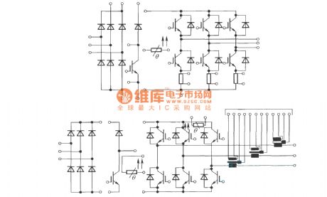
TX-KDl02 MOSFET or IGBT functional block diagram
Published:2011/4/8 0:37:00 Author:muriel | Keyword: MOSFET, IGBT, functional block diagram
View full Circuit Diagram | Comments | Reading(543)
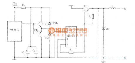
TX-KD501 application cording diagram(driver)
Published:2011/4/8 0:37:00 Author:muriel | Keyword: TX-KD501, application cording diagram, driver
View full Circuit Diagram | Comments | Reading(590)
The function generator composed of 555 timer
Published:2011/4/18 21:04:00 Author:Ecco | Keyword: function generator , 555 , timer

The chart shows a function generator circuit composed of 555 timer. The circuit consists of a CH7555 timer and some transistors and RC components. It can generate triangle wave, square wave, sine wave, sawtooth and square wave sweep simultaneously. Ramp can be positive or negative. The frequency of various waveforms is adjustable from 0.1Hz ~ 100kHz, the amplitude of square wave is 5 ~ 15V, it can directly drive TTL circuits (power supply is 5V). Nonlinear ramp is below 1%, sine wave distortion is less than 3%.
(View)
View full Circuit Diagram | Comments | Reading(6072)
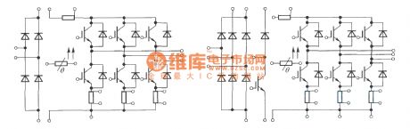
Standard MiniSkiip circuit
Published:2011/4/8 0:36:00 Author:muriel | Keyword: MiniSkiip circuit
View full Circuit Diagram | Comments | Reading(474)
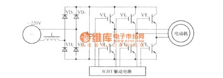
Schematic diagram of Frequency converter control drive main circuit
Published:2011/4/8 0:35:00 Author:muriel | Keyword: Frequency converter, control drive main circuit
View full Circuit Diagram | Comments | Reading(468)
Switching alarm sound generator(KD9561)
Published:2011/4/18 21:37:00 Author:Ecco | Keyword: Switching , alarm sound , generator
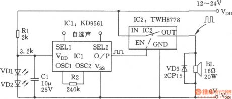
KD9561 is a CMOS four syllables music IC. With an oscilloscope observing the output waveform frequency square wave signal, the logic circuit can be considered as a digital signal. TWH8778 is the high power switching IC, it is suitable for processing digital signals, and it can be connected to CMOS IC directly as its high input impedance. The maximum output frequency of KD9561 is several thousand Hz, and TWH8778 can work up to 15 kHz. So there is not a matter of time digital signal processing when the former controlling the latter,and it should combine both and form a switching amplifying alarm sound generator. It can be used as police cars, ambulances, fire trucks and other alarm generator. Comparing with other linear audio amplifier, it has the advantages of simple structure, high efficiency, excellent cost. Although the sound quality is not perfect, its output power of amplifier could satisfy the requirements of general alarm sound, and the alarm generator does not need high-fidelity. The circuit is as shown in the chart.
(View)
View full Circuit Diagram | Comments | Reading(2131)
Testing EXB850 overcurrent waveform circuit
Published:2011/4/7 22:58:00 Author:muriel | Keyword: overcurrent waveform circuit
View full Circuit Diagram | Comments | Reading(485)
SKHI series driver detection schematic circuit diagram
Published:2011/4/7 22:58:00 Author:muriel | Keyword: driver etection
View full Circuit Diagram | Comments | Reading(442)
Application cording diagram of TX-KDl02
Published:2011/4/8 0:38:00 Author:muriel | Keyword: application cording diagram, KD10X
View full Circuit Diagram | Comments | Reading(439)
Pulse signal source with independently adjustable frequency and pulse(CD4011)
Published:2011/4/18 21:10:00 Author:Ecco | Keyword: Pulse signal source , independently , adjustable, frequency , pulse


When general pulse generator adjust its oscillation frequency, the signal pulse width is also changed. Conversely, when it needs to change the pulse width, the oscillation frequency is changed. The circuit can make the pulse width and frequency be adjusted separately, they are independent from each other. The circuit shows in Fig.
(View)
View full Circuit Diagram | Comments | Reading(1293)
| Pages:2070/2234 At 2020612062206320642065206620672068206920702071207220732074207520762077207820792080Under 20 |
Circuit Categories
power supply circuit
Amplifier Circuit
Basic Circuit
LED and Light Circuit
Sensor Circuit
Signal Processing
Electrical Equipment Circuit
Control Circuit
Remote Control Circuit
A/D-D/A Converter Circuit
Audio Circuit
Measuring and Test Circuit
Communication Circuit
Computer-Related Circuit
555 Circuit
Automotive Circuit
Repairing Circuit