
Circuit Diagram
Index 2072
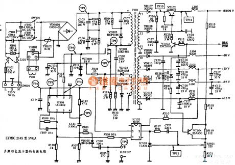
The power supply circuit diagram of LYMIC 214S type SVGA multiple frequency color display
Published:2011/4/14 6:39:00 Author:may | Keyword: power supply, SVGA, multiple frequency, color display
View full Circuit Diagram | Comments | Reading(610)
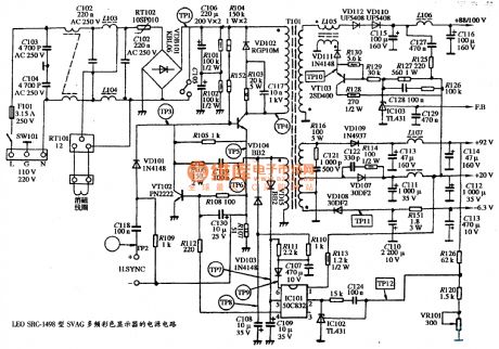
The power supply circuit diagram of LEO SRC-1498 type SVGA multiple frequency color display
Published:2011/4/14 6:38:00 Author:may | Keyword: power supply, SVGA, multiple frequency, color display
View full Circuit Diagram | Comments | Reading(558)
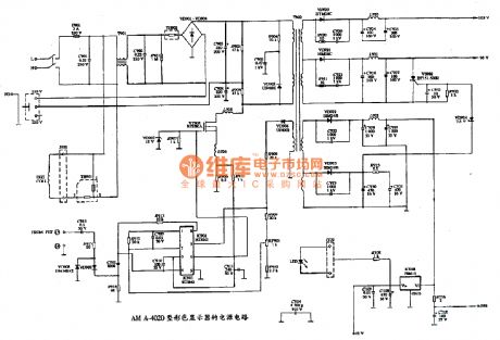
The power supply circuit diagram of AM A-4040 type color display
Published:2011/4/14 6:38:00 Author:may | Keyword: power supply, color display
View full Circuit Diagram | Comments | Reading(717)
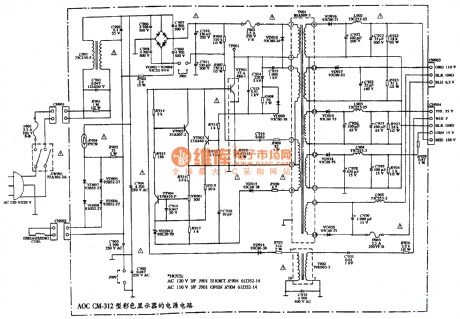
The power supply circuit diagram of AOC CM-312 type color display
Published:2011/4/14 6:37:00 Author:may | Keyword: power supply, color display
View full Circuit Diagram | Comments | Reading(608)
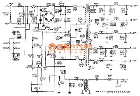
The power supply circuit diagram of AOC CM-314 type color display
Published:2011/4/14 6:36:00 Author:may | Keyword: power supply, color display
View full Circuit Diagram | Comments | Reading(807)
DC 12V sine AC 22Dv, 50N, 10W converter
Published:2011/4/14 4:18:00 Author:may | Keyword: DC 12V sine AC 22Dv, 50N, 10W, converter
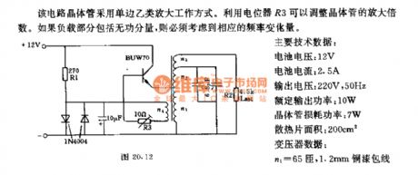
The transistor in this circuit adopts the working mode of single side class b amplification. It can adjust the amplification factor of transistor by potentiometer R3. We must consider the corresponding frequency variation if load part including idle component.
Main technical data:
Battery voltage: 12V
Battery current: 2.5A
Output voltage: 220V, 50Hz
Rated output power: 10W
Transistor loss power: 7W
Cooling plate area: 200cm2
Transformer data:
n1=65turns, 1.2mm copper lacquered wire
n2=650turns, 0.29mm copper lacquered wire
n1=2050turns, 0.14mm copper lacquered wire
n1=100turns, 0.45mm copper lacquered wire
(View)
View full Circuit Diagram | Comments | Reading(797)
MCU and RS232 serial interface wiring diagram circuit
Published:2011/3/25 3:17:00 Author:may | Keyword: MCU and RS232 serial interface wiring diagram

MCU and RS232 serial interface wiring diagram circuit is shown in the diagram:
(View)
View full Circuit Diagram | Comments | Reading(2197)
87lpc76 serial port circuit
Published:2011/3/25 3:15:00 Author:may | Keyword: serial port
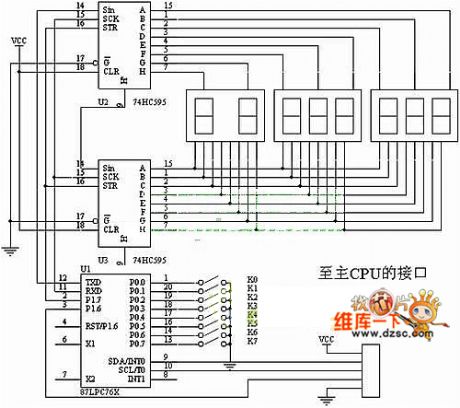
87lpc76 serial port circuit is show in the following diagram:
(View)
View full Circuit Diagram | Comments | Reading(476)
5Hz ~ 5MHz function generator composed of MAX038
Published:2011/4/18 20:17:00 Author:Ecco | Keyword: 5Hz ~ 5MHz , function generator

The 5Hz ~ 5MHz function generator circuit is shown in the chart. The circuit is a 5Hz ~ 5MHz function generator circuit, which could output the square wave, sine wave and triangular wave according to the need. The integrated circuit MAX038 is a special function generator which sets the oscillation frequency by the current of the input current terminal IIN. It changes the reference voltage into current by a resistor, the current flowing the end of FADJ is used to adjust the frequency. The frequency range of the circuit is set as multiples of 10. The timing capacitor is changed in the range of 75pF ~ 10μF. As the wire connection has an effect on working capacitor when the frequency is 5MHz, it could increase a CTc variable condenser in 50pF connecting to 75pF working capacitor in parallel, and it is easy to correct the high frequency. Frequency setting potentiometer PR1 adopts a resistor with 10 laps. The circuit is characterized by simple structure, adjustable components, reliable working.
(View)
View full Circuit Diagram | Comments | Reading(9216)
The function generator using 8038
Published:2011/4/18 20:16:00 Author:Ecco | Keyword: function generator
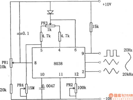
The function generator using 8038 is shown in the chart. The function generator using integrated circuit chip 8038 can get square, triangle wave and sine wave simultaneously. Triangular wave is directly formed by discharging from the constant capacitor; square wave received by the controlling signal; sine wave received by the triangular wave passing the approximation circuit. The sine curve obtained like this is not a smooth sine curve, and the distortion is about 1% and it can meet the needs of general purpose. The potentiometer PR1 in the circuit is used to adjust the frequency, its range is in 20Hz to 20kHz. PR2 is used to adjust the waveform distortion, PR3 is used to adjust the duty cycle of the waveform.
(View)
View full Circuit Diagram | Comments | Reading(7021)
Multi-functional sound generator composed of NE555、CC4051
Published:2011/4/18 20:13:00 Author:Ecco | Keyword: Multi-functional sound generator

This circuit is mainly used for regular alarm and audio generator in electronic toys. The circuit is characterized by a large range of supply voltage changing adaptation, it can work under 4 ~ 18V. Tone and tempo do not change by the altering of supply voltage, it can be used to indicate various states.
(View)
View full Circuit Diagram | Comments | Reading(1603)
The power supply circuit diagram of 61、IBM 5153-002 color displays
Published:2011/4/18 20:12:00 Author:Ecco | Keyword: power supply , color display
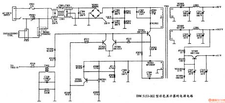
What shows below are the circuit diagrams collected by our site, and here are the pictures of the power supply circuit diagram of 61、IBM 5153-002 color displays.
(View)
View full Circuit Diagram | Comments | Reading(866)
Clapp signal generator
Published:2011/4/18 20:11:00 Author:Ecco | Keyword: Clapp , signal generator
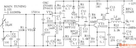
The clapp signal generator is shown in the chart. VTl isa variable LC oscillator composed of the typical clapp circuit in high stability. The feedback factor is decided by the capacitors C4、C5, and their capacitance is so high that it can effectively reduce the short-term fibrillation rate drift caused by the changing of capacitance when starting up.
(View)
View full Circuit Diagram | Comments | Reading(802)
0.1Hz~500kHz signal source made by LM567
Published:2011/4/18 20:12:00 Author:Ecco | Keyword: 0.1Hz~500kHz, signal source
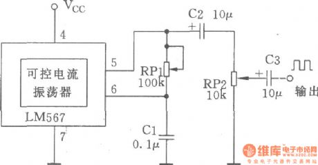
The manifold block LM567 is a stable PLL circuit with synchronous amplitude locking and detecting. The internal manifold controllable current oscillator can make a simple small adjustable low-frequency signal source, it's very easy for maintenance. Circuit is as shown in the chart.
(View)
View full Circuit Diagram | Comments | Reading(1625)
Darkroom time controller composed of 555
Published:2011/4/18 20:00:00 Author:Ecco | Keyword: Darkroom , time controller, 555

View full Circuit Diagram | Comments | Reading(530)
Voltage-controlled sinusoidal oscillator composed of MC1046B
Published:2011/4/18 20:10:00 Author:Ecco | Keyword: Voltage-controlled , sinusoidal , oscillator
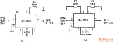
The voltage-controlled sinusoidal oscillator circuit is shown in the chart. It is composed of MC1046B. When the controlling input voltage is 0 ~ 5V, the outputcan get the sine signal withfrequencyfrom 0 ~ 20kHz.The frequency range is decided by the resistor R1 and capacitor C, changing the resistors and capacitorscould change the oscillation frequency. If the external resistor R2 connects topin 12 , oscillation frequency range could be changed. If you choose R2 = 2R1, the oscillation frequency becomes 10 ~ 30kHz.
(View)
View full Circuit Diagram | Comments | Reading(1057)
Bell ringing signal generator
Published:2011/4/18 20:09:00 Author:Ecco | Keyword: bell ringing , signal generator
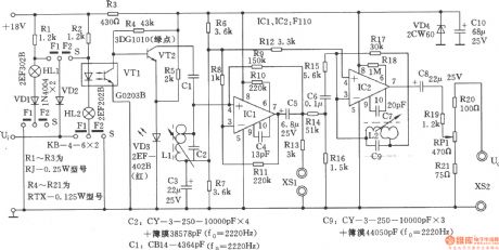
Bell ringing signal generator is generally used as calling signal source of communications equipment. Calling sending oscillator can send shift frequency calling signal under the control of automatic switching system, to choose the user for opposite person. Klingel signal generator is composed of shift frequency control circuit, LC shift frequency oscillator, output circuit, the circuit is shown as the chart.
(View)
View full Circuit Diagram | Comments | Reading(886)
Bailing rolling massager circuit
Published:2011/4/18 20:02:00 Author:Ecco | Keyword: Bailing , rolling , massager

View full Circuit Diagram | Comments | Reading(811)
Reading and writing posture reminder
Published:2011/4/18 19:59:00 Author:Ecco | Keyword: Reading , writing , posture , reminder
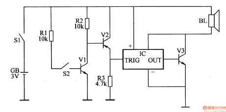
When primary and secondary students do reading and writing, it is easy to affect the visual and physical health with wrong sitting position for a long time. This example describes the reading and writing posture reminder, it can help the user correct the posture by emitting the warning sounds when the position of the user is not correct.
The working principle.
Reading and writing posture reminder circuit is composed ofelectronic switch circuit, alarm circuit and power circuit, it is shown as the Figure 9-160.
Electronic switching circuit is composedof the glass shell mercury switch S2, the transistor Vl, V2 and resistors
Alarm circuitis composed ofthe integrated circuit IC, audio amplification tube V3and speaker BL.
The power supply circuit is composed of power supply GB and power switch Sl.
Turning the power switch Sl, the powersupply GBprovides operating voltage for the machine.
(View)
View full Circuit Diagram | Comments | Reading(707)
Large current charge circuit composed of U2403B constant temperature current charging timer
Published:2011/4/18 20:36:00 Author:Nicole | Keyword: large current, constant temperature current, charging timer

View full Circuit Diagram | Comments | Reading(525)
| Pages:2072/2234 At 2020612062206320642065206620672068206920702071207220732074207520762077207820792080Under 20 |
Circuit Categories
power supply circuit
Amplifier Circuit
Basic Circuit
LED and Light Circuit
Sensor Circuit
Signal Processing
Electrical Equipment Circuit
Control Circuit
Remote Control Circuit
A/D-D/A Converter Circuit
Audio Circuit
Measuring and Test Circuit
Communication Circuit
Computer-Related Circuit
555 Circuit
Automotive Circuit
Repairing Circuit