Circuit Diagram
Index 2075
Toy car remote control circuit diagram
Published:2011/4/18 5:04:00 Author:Rebekka | Keyword: Toy car remote control


Toy car remote control transmitter circuit.
Toy car remote control receiver circuit.
(a) is receive circuit. It contains seven output ABCDEFG. They Control the steering respectively(b); Left and right turn signal(Figure c); Drive motor (Figure d); Musical sound circuit(Figure e); Brake solenoid and driver rear brake light LED5LED6 lights; Before and after the headlight switch (Fig. g); power supply (Figure h).
(View)
View full Circuit Diagram | Comments | Reading(2327)
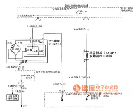
Buick GL8 air flow meter and evaporative emission circuit
Published:2011/4/18 7:19:00 Author:Jessie | Keyword: air flow meter, evaporative emission
View full Circuit Diagram | Comments | Reading(612)
100 in 1 TV multi-function remote control circuit(Compatible with all the co-RM-33C, NT66P13)
Published:2011/4/18 6:49:00 Author:Rebekka | Keyword: TV multi-function remote control

100 in 1 TV multi-function remote control circuit(Compatible with all the co-RM-33C, NT66P13) is shown as above. (View)
View full Circuit Diagram | Comments | Reading(416)
45 in 1 Multi-function air-conditioning remote control circuit
Published:2011/4/18 6:51:00 Author:Rebekka | Keyword: Multi-function remote control , air-conditioning
View full Circuit Diagram | Comments | Reading(383)
Super-regenerative type radio receiver circuit diagram
Published:2011/4/18 6:50:00 Author:Rebekka | Keyword: Super-regenerative type, Radio receiver

Intermittent oscillation frequency of the circuit is about l20kHz. (View)
View full Circuit Diagram | Comments | Reading(1558)
Coal gas accident alarm circuit diagram
Published:2011/4/18 2:34:00 Author:Rebekka | Keyword: Coal gas accident alarm

The circuit is match with gas stove. When the flame appears, it provides a stable airflow for the main nozzle gas relay. Radiation caused by the intermittent flame flash will produce low frequency signal. The amplified signal will produce pule to charge the capacitor. IR5 will be turned on and drive the alarm by relay. There isn't flame flash or pulse, the condenser discharge and IR5 will be stopped.
(View)
View full Circuit Diagram | Comments | Reading(674)
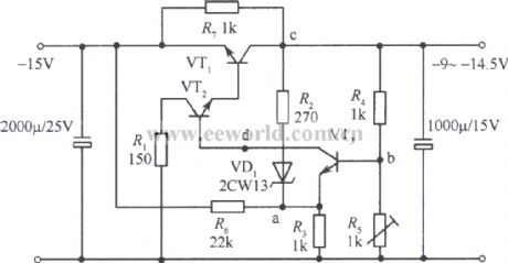
-9~-l4.5v Collector output regulated voltage power supply circuit
Published:2011/3/22 22:59:00 Author:muriel | Keyword: -9~-l4.5v, Collector , output , regulated voltage power supply
View full Circuit Diagram | Comments | Reading(683)
CMOS Logic probe circuit
Published:2011/3/22 1:54:00 Author:muriel | Keyword: CMOS, Logic probe circuit
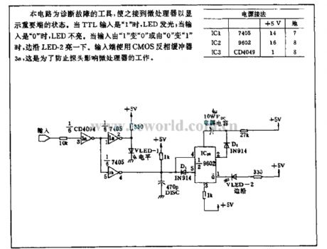
This circuit is a tool for the diagnosis of failure to display important state after link to microprocessors. When the TTL input is 1 , LED light; when the input is 0 , LED does not light. When the input from the 1 to 0 or 0 to 1 , the edge of the LED-2 light once. Input end use CMOS inverter buffer 3a, that can prevent the probe influence microprocessor. (View)
View full Circuit Diagram | Comments | Reading(1235)
Naiqi YB-831A rolling massage machines circuit
Published:2011/4/18 9:12:00 Author:Ecco | Keyword: Naiqi , rolling , massage machines
View full Circuit Diagram | Comments | Reading(670)
Circuit of using buzzer instead of figure light
Published:2011/4/13 22:02:00 Author:Nicole | Keyword: buzzer, figure light
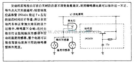
If using a motor to watch indicator light, it will not decern easily weather the light is on or off in daytime, but the buzzer circuit can compensate for it. To turn on the ignition switch, the JFET 2N5434 also will be turned on after about 7s delayed time, so in the process of starting car and increasing oil pressure normally, the buzzer will not to ring; then using indicator light to watch oil pressure sensor and motor temperature sensor. This circuit can be fixed in those not being used buzzer plastic casing of bridge house. (View)
View full Circuit Diagram | Comments | Reading(546)
Modulated photoelectric isolation circuit
Published:2011/4/14 21:40:00 Author:Nicole | Keyword: photoelectric isolation
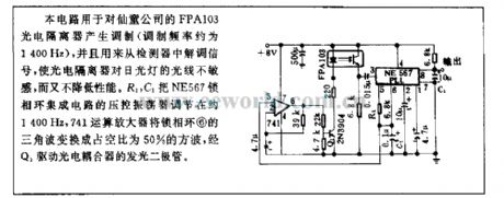
This circuit is used to modulate FPA103 photoelectric isolator which is produced by Xiantong Company, it is also used to regulate singal from detector, making photoelectric isolator insensitive to the light of fluorescent lamp, and it will not reduce its performance. The VCO of NE567 PLLIC is adjusted to about 1400Hz by R1, C1, 741 operation amplifier changes the PLL⑥ triangular wave into square wave with 50% duty ratio, then to drive photoelectric coupler LED through Q1. (View)
View full Circuit Diagram | Comments | Reading(419)
Polarity reversal drive circuit
Published:2011/4/6 21:30:00 Author:Nicole | Keyword: Polarity reversal drive

9614 polarity reversal driver is transported to HCPL-2602 Photo coupler receiver through shield wire, twisted-pair or coaxial cable. In receiver input terminal, to connect a Schottky diode, it can impove the data transmission speed greatly. When tPHL(transmission delay time of turning into low output level) and tPLH(transmission delay time of turning into high output level) is closed to equal, there is the maximum data transmission speed. (View)
View full Circuit Diagram | Comments | Reading(421)
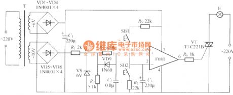
Dimming light circuit with operational amplifier
Published:2011/4/18 9:36:00 Author:Nicole | Keyword: dimming light, operational amplifier
View full Circuit Diagram | Comments | Reading(439)
Dimming light circuit with parameter solid state relay
Published:2011/4/18 9:35:00 Author:Nicole | Keyword: dimming light, solid state relay


The relation between input resistance of 3, 4 foot and 5, 6 foot pressure drop is as below:
(View)
View full Circuit Diagram | Comments | Reading(477)
Touch delay light circuit adopted power switch integrated circuit
Published:2011/4/18 9:29:00 Author:Nicole | Keyword: delay light, power switch

The delay time is determined by the capacity of C2, the figure data is about 25s. If it is needed to delay time, you can increase its capacity. Besides, the touch time also has influence on the circuit delay time. (View)
View full Circuit Diagram | Comments | Reading(496)
SH-808 festival color lamp with multiple music synchronous phonation control circuit 2
Published:2011/4/18 9:24:00 Author:Nicole | Keyword: festival color lamp, music
View full Circuit Diagram | Comments | Reading(381)
SH-808 festival color lamp with multiple music synchronous phonation control circuit 1
Published:2011/4/18 9:21:00 Author:Nicole | Keyword: festival color lamp, music
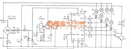
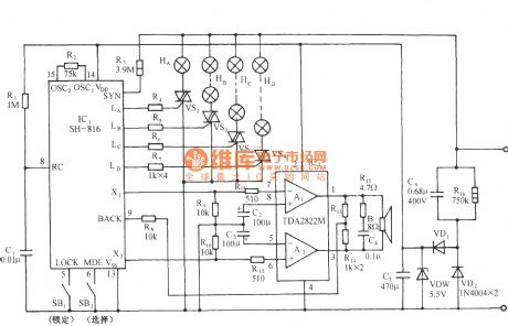
The cirucit is as shown. It consists of rhythm pulse generator, light control circuit, music amplifier circuit and AC depressurization rectifier circuit. The core composition of light control circuit is festival color lamp control special integrated circuit. (View)
View full Circuit Diagram | Comments | Reading(802)
SH-811 festival color lamp with piano music control circuit
Published:2011/4/18 9:14:00 Author:Nicole | Keyword: festival color lamp, piano music
View full Circuit Diagram | Comments | Reading(388)
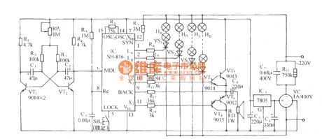
SH-816 multi-pattern festival color lamp with piano music control circuit
Published:2011/4/18 9:13:00 Author:Nicole | Keyword: festival color lamp, piano music
View full Circuit Diagram | Comments | Reading(775)
SH-816 festival color lamp with piano music automatic transformation control circuit
Published:2011/4/18 9:11:00 Author:Nicole | Keyword: festival color lamp, piano music
View full Circuit Diagram | Comments | Reading(350)
| Pages:2075/2234 At 2020612062206320642065206620672068206920702071207220732074207520762077207820792080Under 20 |
Circuit Categories
power supply circuit
Amplifier Circuit
Basic Circuit
LED and Light Circuit
Sensor Circuit
Signal Processing
Electrical Equipment Circuit
Control Circuit
Remote Control Circuit
A/D-D/A Converter Circuit
Audio Circuit
Measuring and Test Circuit
Communication Circuit
Computer-Related Circuit
555 Circuit
Automotive Circuit
Repairing Circuit
