Circuit Diagram
Index 2065
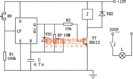
Exposure timer circuit with D flip-flop
Published:2011/4/19 2:26:00 Author:Jessie | Keyword: Exposure timer, D flip-flop
View full Circuit Diagram | Comments | Reading(842)
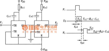
Impulsive delay circuit with J210
Published:2011/4/19 2:27:00 Author:Jessie | Keyword: Impulsive delay
View full Circuit Diagram | Comments | Reading(777)
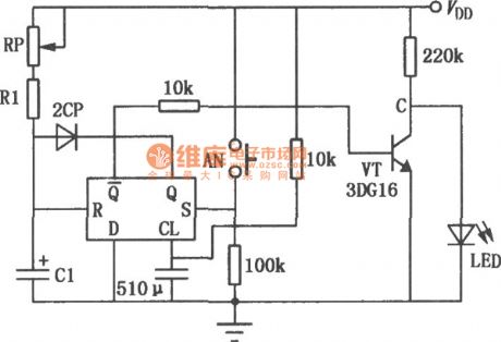
Timer circuit with D flip-flop
Published:2011/4/19 2:28:00 Author:Jessie | Keyword: Timer, D flip-flop
View full Circuit Diagram | Comments | Reading(848)
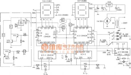
Preset timing countdown timer circuit
Published:2011/4/19 2:29:00 Author:Jessie | Keyword: Preset timing, countdown timer
View full Circuit Diagram | Comments | Reading(2911)
50Hz high-precision time base circuit
Published:2011/4/19 2:45:00 Author:Ecco | Keyword: 50Hz, high-precision, time base circuit
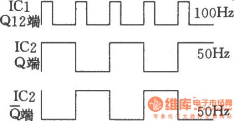
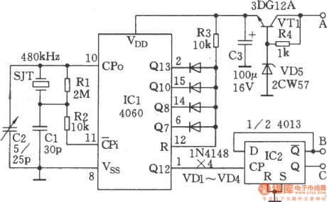
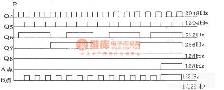
50Hz high-precision time base circuit is shown as the chart. It consists of two CMOS digital integrated circuits and quartz crystal. The circuit generates 50Hz time base signal with accurate frequency and the same duty cycle, the circuit is simple, it iseasy to make. The following picture shows the waveform.
(View)
View full Circuit Diagram | Comments | Reading(1786)
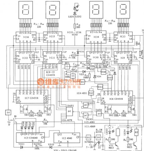
Digital display four high-precision general timer circuit
Published:2011/4/19 2:47:00 Author:Jessie | Keyword: Digital display, four high-precision, general timer
View full Circuit Diagram | Comments | Reading(1056)
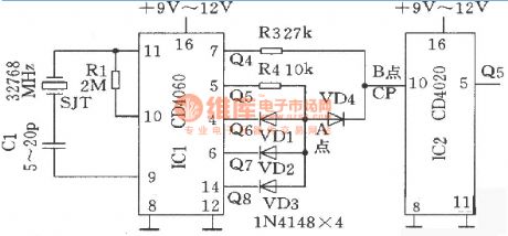
The time-base circuit produing 60 Hz signal composed of 32768Hz crystal SJT
Published:2011/4/19 2:41:00 Author:Ecco | Keyword: time-base circuit , 60 Hz signal , crystal, SJT
View full Circuit Diagram | Comments | Reading(657)
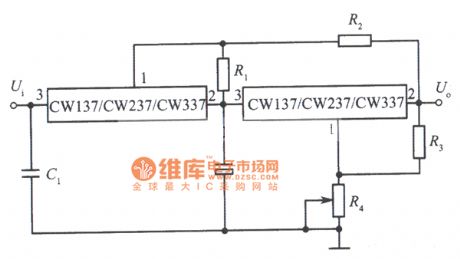
Tracking integrated manostat circuit with CW137
Published:2011/4/19 3:37:00 Author:Jessie | Keyword: Tracking, integrated manostat
View full Circuit Diagram | Comments | Reading(523)
Wanjiale ZLP-68 ZLP-78 ZLP-88 tableware alexipharmic ark circuit
Published:2011/4/19 3:34:00 Author:Jessie | Keyword: tableware alexipharmic ark
View full Circuit Diagram | Comments | Reading(540)
Wanjiale YLD-36A YLD-46A YLD-56A horizontal tableware alexipharmic ark circuit
Published:2011/4/19 3:33:00 Author:Jessie | Keyword: horizontal, tableware alexipharmic ark
View full Circuit Diagram | Comments | Reading(481)
Wanjiale RLP-48 tableware alexipharmic ark circuit
Published:2011/4/19 3:32:00 Author:Jessie | Keyword: tableware alexipharmic ark
View full Circuit Diagram | Comments | Reading(584)
Wanhe ZTP-88 computer control electronics alexipharmic ark circuit
Published:2011/4/19 3:31:00 Author:Jessie | Keyword: computer control, electronics alexipharmic ark
View full Circuit Diagram | Comments | Reading(554)
Wanhe ZTP-76A Multi-functional electronic alexipharmic ark circuit
Published:2011/4/19 3:26:00 Author:Jessie | Keyword: Multi-functional, electronic alexipharmic ark
View full Circuit Diagram | Comments | Reading(631)
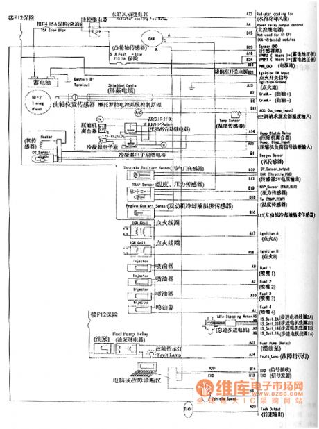
Shanghai GM WuLing MOTOROLA electronic control system circuit
Published:2011/4/19 3:25:00 Author:Jessie | Keyword: electronic control system
View full Circuit Diagram | Comments | Reading(438)
Drawing light pen circuit diagram
Published:2011/4/18 1:52:00 Author:Rebekka | Keyword: Drawing light pen

The circuit uses the way of short cut off input to avoid input data confusion. So that the ability of drawing light pen on the display will be improved. The resistance of R1 is decided by light pen. For H-35 light pen of Texas lnstrumens, R1 is 1MΩ. Monostable NO.1 produces 200ns pulse that is rate constant so that l or 0 stored in the cathode-ray oscilloscope graphical interface can be stored in 2102 memory. (View)
View full Circuit Diagram | Comments | Reading(1268)
New high-voltage warning device 2
Published:2011/4/19 2:02:00 Author:Rebekka | Keyword: high-voltage warning device
View full Circuit Diagram | Comments | Reading(471)
Children lost warning device circuit diagram(NE555/TDA7000)
Published:2011/4/18 4:41:00 Author:Rebekka | Keyword: Children lost warning device

FM transmitter circuit contains low-frequency modulation of oscillator and carrier frequency oscillator transmitter circuit.It is shown in figure (a). The receiving circuit is shown in figure(b). (View)
View full Circuit Diagram | Comments | Reading(1597)
Microwave sensor module RD627A application circuit diagram
Published:2011/4/18 4:58:00 Author:Rebekka | Keyword: Microwave sensor module
View full Circuit Diagram | Comments | Reading(1092)
Centigrade thermometer circuit with thermocouple cold end temperature compensator AD594/595
Published:2011/4/18 20:04:00 Author:Jessie | Keyword: Centigrade thermometer, thermocouple cold end temperature compensator
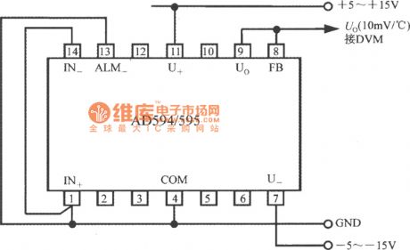
AD594/595 can be also configurated into centigrade thermometer, and it is as shown in the diagram. At this time, IN+, IN- should connect to COM, output voltage Uo's temperature coefficient is 10mV/℃, and it can be sent to DVM to measure and display the temperature. (View)
View full Circuit Diagram | Comments | Reading(1095)
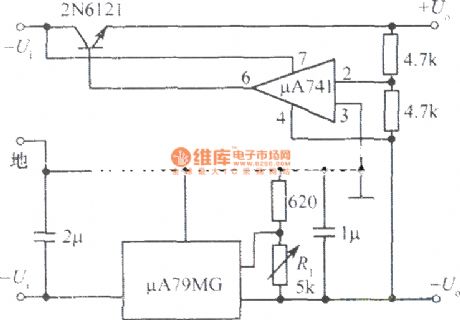
±5--±20V slave tracking stabilized voltage supply plus side driven pulley minus side
Published:2011/4/2 1:08:00 Author:may | Keyword: ±5--±20V, slave tracking, stabilized voltage supply, plus side driven pulley minus side
View full Circuit Diagram | Comments | Reading(635)
| Pages:2065/2234 At 2020612062206320642065206620672068206920702071207220732074207520762077207820792080Under 20 |
Circuit Categories
power supply circuit
Amplifier Circuit
Basic Circuit
LED and Light Circuit
Sensor Circuit
Signal Processing
Electrical Equipment Circuit
Control Circuit
Remote Control Circuit
A/D-D/A Converter Circuit
Audio Circuit
Measuring and Test Circuit
Communication Circuit
Computer-Related Circuit
555 Circuit
Automotive Circuit
Repairing Circuit
