Circuit Diagram
Index 2063
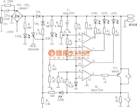
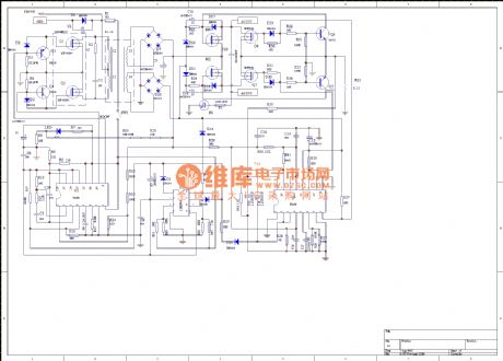
Ericsson 788 travel type charger circuit diagram
Published:2011/4/19 8:58:00 Author:May | Keyword: Ericsson 788, travel type charger
View full Circuit Diagram | Comments | Reading(1060)
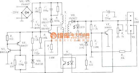
SPN4096A charger circuit diagram
Published:2011/4/19 8:56:00 Author:May | Keyword: charger
View full Circuit Diagram | Comments | Reading(728)
12V Pb acid storage battery charging circuit
Published:2011/4/19 8:54:00 Author:May | Keyword: 12V, Pb acid storage battery, charging
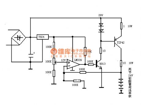
It can charge to two series 12V Pb acid storage battery by this circuit.
(View)
View full Circuit Diagram | Comments | Reading(1266)
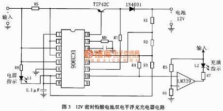
12V seal Pb acid dual level folating charger circuit
Published:2011/4/19 8:51:00 Author:May | Keyword: 12V, seal, Pb acid, dual level, folating charger
View full Circuit Diagram | Comments | Reading(1021)
The self-excited multivibrator composed of CC4093
Published:2011/4/19 6:47:00 Author:Ecco | Keyword: self-excited , multivibrator
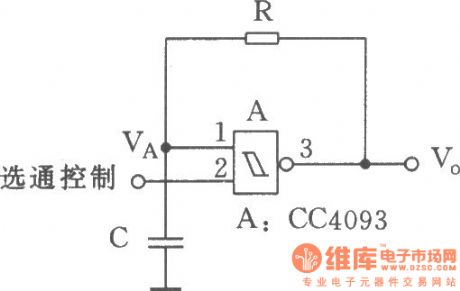
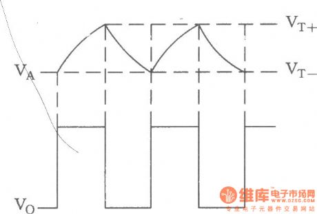
It needs a resistance and a capacitor connecting externally when forming a multivibrator by Schmidt trigger. The circuit is used to the low frequency vibration source which has lower demand for accuracy, and the vibration is controlled. The circuit in the figure is a self-excited much harmonic oscillator composed of four 2 input Schmidt trigger.
(View)
View full Circuit Diagram | Comments | Reading(551)
Electronic checking tone ware composed of CC4040
Published:2011/4/19 6:39:00 Author:Ecco | Keyword: Electronic, checking tone ware
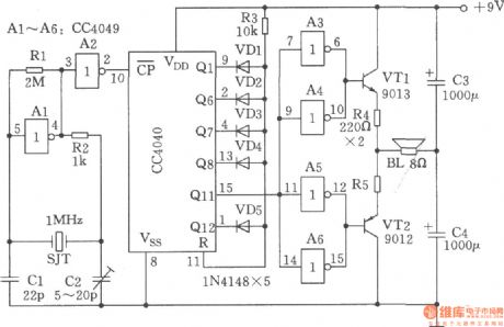
The chart shows the electronic checking tone ware composed of CC4040. The circuit could produce 440Hz international standard A sound, it can be used as checking tone ware for band.
(View)
View full Circuit Diagram | Comments | Reading(502)
450 Audio signal generator
Published:2011/4/19 2:54:00 Author:Ecco | Keyword: Audio, signal , generator
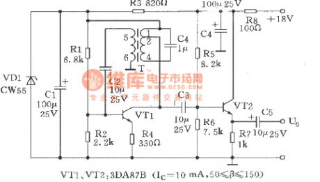
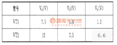
The oscillator is the services signal source for communication user . Working principle is as shown. It consists of VTl, VT2, and other related components. VTl using transformer T to couple oscillation signal, VT2 is the common collector buffer amplifier circuit, the emitter output. T transformer with 1-4 winding and the capacitor C4 form a selecting frequency network. In order to prevent magnetic saturation of T, T is connected to the collector of VTl by the 1-2 tap, 5-6 of T is the feedback loop. Detection: The DC-bit of pin-to-ground (reference value) is as shown in the table.
(View)
View full Circuit Diagram | Comments | Reading(437)
3-1 count down circuit composed of CD4013
Published:2011/4/19 4:37:00 Author:Ecco | Keyword: 3-1 , count down circuit

In digital circuits, sometimes it needs pulse a divider circuit which could minus a few input pulse. The appropriate combination ofCD4013 and feedback door can achieve any pulse subtraction circuit. Figure 3-1 shows 3-1 count down circuit composed of CD4013.
(View)
View full Circuit Diagram | Comments | Reading(1872)
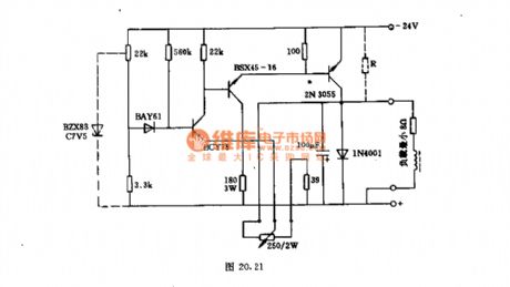
24V/3A transistor voltage regulator
Published:2011/4/19 3:06:00 Author:May | Keyword: 24V/3A, transistor, voltage regulator
View full Circuit Diagram | Comments | Reading(1682)
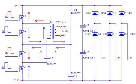
Full bridge circuit diagram
Published:2011/4/19 2:12:00 Author:May | Keyword: Full bridge
View full Circuit Diagram | Comments | Reading(621)
24V DC 220V AC 100W push pull chopper
Published:2011/4/19 3:16:00 Author:May | Keyword: 24V DC, 220V AC, 100W, push pull, chopper
24V DC power supply (such as storage battery) can offer power to this circuit. Controlled by chopper, it can output 220V, 50Hz AC. The main technical data of this circuit:work voltage: 24V (the maximum is 30V)no-load current: 1.15Aoutput voltage: 220V, 50Hzoutput power: 100Wefficiency: 74%The data of transformer:n1=n2=9 turns, 0.42 copper enamelled wiren3=n4=81 turns, 1.2mm copper enamelled wiren5=875 turns, 0.42 copper enamelled wire (View)
View full Circuit Diagram | Comments | Reading(587)
120V/25mA DC voltage converter
Published:2011/4/19 3:31:00 Author:May | Keyword: 120V/25mA, DC voltage converter
This circuit is formed according to the principle of positive breakover convertor. That is to output power to load when the transistor is breaking over. We add diode D1 in its loop for the purpose of overtop base-emitter voltage on transistor. Start-oscillation button connected betweent resistor R1 and R2 is assisted start device. Meanwhile it can prevent the add of base current when load current is increasing. So this circuit has the function of short circuit protection.The data of transformer:winding n1=40 turns, 0.32 copper enamelled wiren2=12 turns, 0.15 copper enamelled wiren3=420 turns, 0.1mm copper enamelled wire (View)
View full Circuit Diagram | Comments | Reading(362)
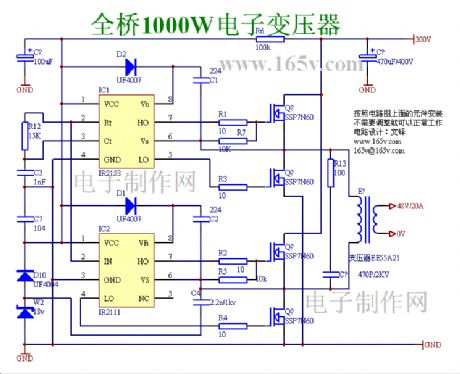
No adjustment full bridge 1000W electronic transformer
Published:2011/4/19 3:35:00 Author:May | Keyword: No adjustment, full bridge, 1000W, electronic transformer
View full Circuit Diagram | Comments | Reading(3242)
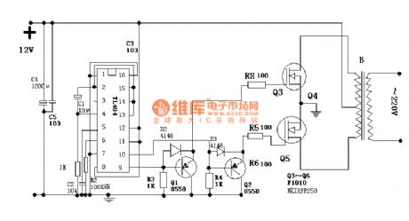
Inverter circuit 15
Published:2011/4/19 2:52:00 Author:May | Keyword: Inverter
250W controlled silicon inverter
(View)
View full Circuit Diagram | Comments | Reading(483)
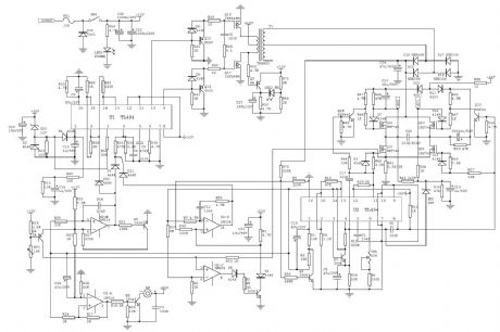
Inverter circuit 16
Published:2011/4/19 2:53:00 Author:May | Keyword: Inverter
View full Circuit Diagram | Comments | Reading(2324)
Inverter circuit 2
Published:2011/4/19 2:54:00 Author:May | Keyword: Inverter
View full Circuit Diagram | Comments | Reading(2461)
Inverter circuit 21
Published:2011/4/19 2:54:00 Author:May | Keyword: Inverter
View full Circuit Diagram | Comments | Reading(2381)
Inverter circuit 22
Published:2011/4/19 2:55:00 Author:May | Keyword: Inverter
View full Circuit Diagram | Comments | Reading(493)
Inverter circuit 23
Published:2011/4/19 2:56:00 Author:May | Keyword: Inverter
View full Circuit Diagram | Comments | Reading(945)
Inverter circuit 25
Published:2011/4/19 2:57:00 Author:May | Keyword: Inverter
View full Circuit Diagram | Comments | Reading(547)
| Pages:2063/2234 At 2020612062206320642065206620672068206920702071207220732074207520762077207820792080Under 20 |
Circuit Categories
power supply circuit
Amplifier Circuit
Basic Circuit
LED and Light Circuit
Sensor Circuit
Signal Processing
Electrical Equipment Circuit
Control Circuit
Remote Control Circuit
A/D-D/A Converter Circuit
Audio Circuit
Measuring and Test Circuit
Communication Circuit
Computer-Related Circuit
555 Circuit
Automotive Circuit
Repairing Circuit
