
Circuit Diagram
Index 2064
Inverter circuit 3
Published:2011/4/19 2:57:00 Author:May | Keyword: Inverter
View full Circuit Diagram | Comments | Reading(2965)
Inverter circuit 5
Published:2011/4/19 2:58:00 Author:May | Keyword: Inverter
View full Circuit Diagram | Comments | Reading(2444)
Inverter circuit 6
Published:2011/4/19 2:59:00 Author:May | Keyword: Inverter
View full Circuit Diagram | Comments | Reading(2260)
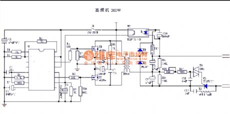
A simple and easy homemade high performance sine wave inverter
Published:2011/4/19 3:03:00 Author:May | Keyword: sine wave, inverter
This inverter adopts three order frequency doubling SPWM modulation. (View)
View full Circuit Diagram | Comments | Reading(5389)
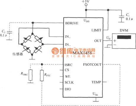
Digital pressure tester circuit with digital pressure signal disposal device MAX1458
Published:2011/4/18 21:29:00 Author:Jessie | Keyword: Digital pressure tester, digital pressure signal disposal device
View full Circuit Diagram | Comments | Reading(385)
Precision bridge isolated amplifier circuit with ISO101
Published:2011/4/18 21:39:00 Author:Jessie | Keyword: bridge isolated amplifier
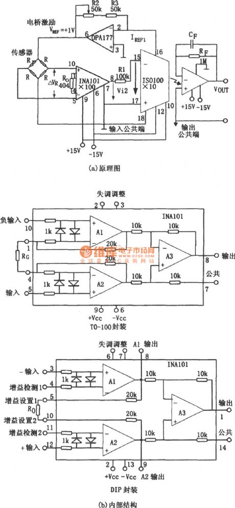
As shown in figureis precision bridge isolated amplifier circuit. Bridge circuit is widely used in automatic control, test, and data acquisition system. Figure (a) is a kind of high precision and high gain bridge isolated amplifier circuit. The sensor Rin bridge can be heat-sensitive, photosensitive or thermistor, etc. The signal voltage of sampling bridgeis single polarity signal, its value is 0~-10mV. This input signal firstamplifiered byhigh precision instrument INA101, and the voltage amplifier multiples of this amplifier is 100. INA101's internal circuit diagrams are as shown in figure (b), (c). (View)
View full Circuit Diagram | Comments | Reading(633)
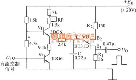
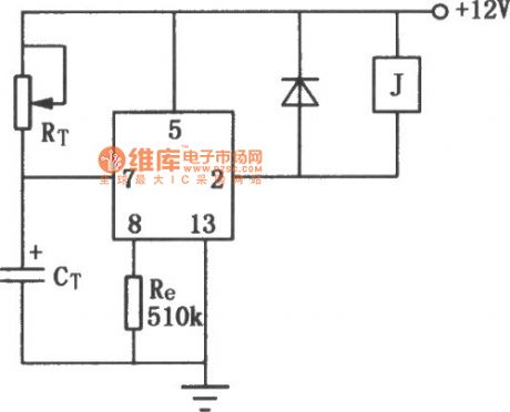
Single junction transistor controllable pulse generator circuit
Published:2011/4/18 22:45:00 Author:Jessie | Keyword: Single junction transistor, controllable pulse generator
View full Circuit Diagram | Comments | Reading(753)
Prompt action circuit with JEC-2
Published:2011/4/19 1:57:00 Author:Jessie | Keyword: Prompt action
View full Circuit Diagram | Comments | Reading(652)
Bidirectional SCR dimming light circuit with bidirectional trigger diode
Published:2011/4/19 4:21:00 Author:Nicole | Keyword: Bidirectional SCR, dimming light, bidirectional trigger diode

View full Circuit Diagram | Comments | Reading(687)
WT8089 16 kinds color lamp patterns with 8 songs controllor
Published:2011/4/19 4:30:00 Author:Nicole | Keyword: color lamp, controllor

View full Circuit Diagram | Comments | Reading(469)
Touch delay light circuit with digital circuit (1)
Published:2011/4/19 4:00:00 Author:Nicole | Keyword: delay light, digital circuit
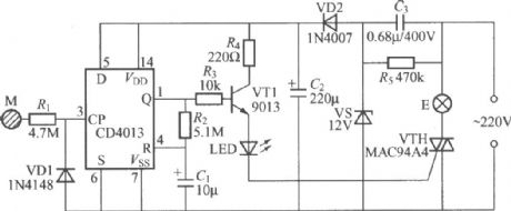
The figure is as shown, it is a touch delay light with CD4013 digital integrated circuit, the circuit consists of C3 depressurization, VD2 rectifier and VS steady voltage, after connecting to power supply, two sides of C2 can output 12V stable DC voltage to supply to the whole switch power utilization. (View)
View full Circuit Diagram | Comments | Reading(1442)
Touch delay light circuit with digital circuit (3)
Published:2011/4/19 4:07:00 Author:Nicole | Keyword: delay light, digital circuit

The figure is as shown, it is a touch delay light with CD4069 digital integrated circuit, it adopts two-wire system connection, it can instead of ordinary light switch directly, it is not needed to change the indoor original wiring. The circuit delay time is determined by the discharge time of R3, C1, the data is about 1min. (View)
View full Circuit Diagram | Comments | Reading(714)
Delay light circuit with special integrated circuit
Published:2011/4/19 3:25:00 Author:Nicole | Keyword: Delay light

The figure is delay light with light control special integrated circuit, the circuit is very simple. In figure, HL2102 IC is produced by Wuxi asic micro electronics oc.,ltd. (http//www.wxasic.corn) it is a light control timing special integrated circuit. This circuit is used to light at night when you get up, when you want to use it just press the push-button switch SB, the light E will light, delay few seconds then the light will off automatically. When the light is on, if you press the SB again, then the light E will off immediately. (View)
View full Circuit Diagram | Comments | Reading(523)
Touch delay light circuit with digital circuit (2)
Published:2011/4/19 4:02:00 Author:Nicole | Keyword: delay light, digital circuit

View full Circuit Diagram | Comments | Reading(410)
Stepless dimming light circuit with special integrated circuit(HT7700A)
Published:2011/4/19 3:31:00 Author:Nicole | Keyword: Stepless dimming light
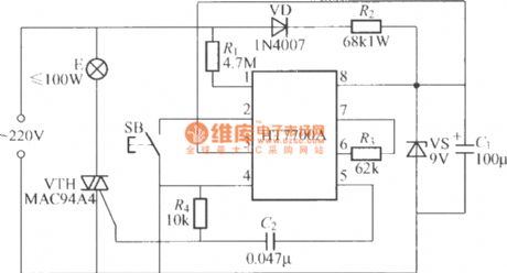
The circuit is as shown, it is a keyed stepless dimming light with HT7700A dimming special integrated circuit, it uses SB single key control, the dimming brightness has 96 levels changes. (View)
View full Circuit Diagram | Comments | Reading(496)
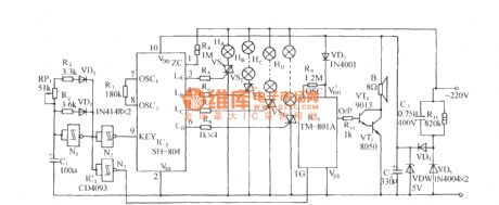
SH-804 festival multi-pattern color lamp with auspicious drum control circuit
Published:2011/4/19 2:15:00 Author:Nicole | Keyword: multi-pattern color lamp, auspicious drum
View full Circuit Diagram | Comments | Reading(515)
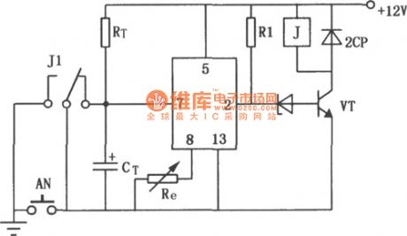
The fridge over voltage, under voltage, power delay protector composed of 556
Published:2011/4/19 3:08:00 Author:Ecco | Keyword: fridge, over voltage, under voltage, power delay , protector

The chart shows a fridge over voltage, under voltage, power delay protector circuit. The circuit consists of over and under voltage sampling circuit, trigger circuit, delay circuit, the buck rectifier circuit. And the buck rectifier circuit provides DC voltage for the entire circuit.
(View)
View full Circuit Diagram | Comments | Reading(3204)
Delay circuit with JEC-2 (2)
Published:2011/4/19 1:56:00 Author:Jessie | Keyword: Delay
View full Circuit Diagram | Comments | Reading(446)
Delay circuit with JEC-2 (1)
Published:2011/4/19 2:24:00 Author:Jessie | Keyword: Delay
View full Circuit Diagram | Comments | Reading(660)
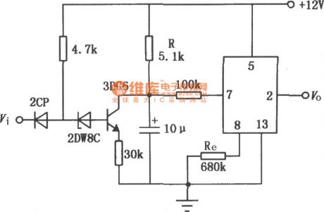
Keyer oscillator
Published:2011/4/19 3:02:00 Author:Ecco | Keyword: keyer, oscillator
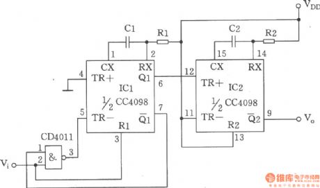
The chart shows a keyer oscillator composed of double monostable triggerCC4098, four 2 input NAND Gate CC4011. The circuit is a keyer oscillator with adjustable keying frequency and duty cycleformed by the monostable trigger, it ismainly usedfor the low frequency signal generatorrequiring less precision.
(View)
View full Circuit Diagram | Comments | Reading(12)
| Pages:2064/2234 At 2020612062206320642065206620672068206920702071207220732074207520762077207820792080Under 20 |
Circuit Categories
power supply circuit
Amplifier Circuit
Basic Circuit
LED and Light Circuit
Sensor Circuit
Signal Processing
Electrical Equipment Circuit
Control Circuit
Remote Control Circuit
A/D-D/A Converter Circuit
Audio Circuit
Measuring and Test Circuit
Communication Circuit
Computer-Related Circuit
555 Circuit
Automotive Circuit
Repairing Circuit