Oscillator Circuit
The adjustable voltage-controlled oscillator with large duty cycle
Published:2011/4/18 1:28:00 Author:Ecco | Keyword: adjustable, voltage-controlled oscillator , large duty cycle | From:SeekIC
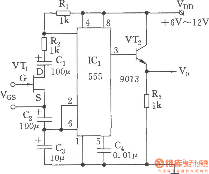
Voltage-controlled oscillator circuit is as shown. 555, R1, R2, C1 ~ C3 and VT1 form a voltage-controlled multivibrator, FET (JFET) VT is voltage-controlled resistor, which can change the impedance between VT-drain (D) and source (S) by changing the gate-source voltage VGs. The coupled capacitors C1、C2 are connected to D,S of VT, they are used to prevent the influence from rest of the circuit of the DC voltage on the JFET. If making coupling capacitors have no effect on the charging and discharging time of time base circuit, the size of C1, C2 should be 10 times of the timing capacitor C3. The advantages of this circuit: the changing of gate-source voltage VGs can make an adjustable variable resistor Rx (can be as large as several hundred kΩ), then it gets the changing of duty cycle and the cycle.
Reprinted Url Of This Article:
http://www.seekic.com/circuit_diagram/Signal_Processing/Oscillator_Circuit/The_adjustable_voltage_controlled_oscillator_with_large_duty_cycle.html
Print this Page | Comments | Reading(3)

Article Categories
power supply circuit
Amplifier Circuit
Basic Circuit
LED and Light Circuit
Sensor Circuit
Signal Processing
Electrical Equipment Circuit
Control Circuit
Remote Control Circuit
A/D-D/A Converter Circuit
Audio Circuit
Measuring and Test Circuit
Communication Circuit
Computer-Related Circuit
555 Circuit
Automotive Circuit
Repairing Circuit
Code: