Oscillator Circuit
The voltage-controlled oscillator with triangular wave and square wave output
Published:2011/4/18 1:59:00 Author:Ecco | Keyword: voltage-controlled oscillator , triangular wave , square wave , output | From:SeekIC
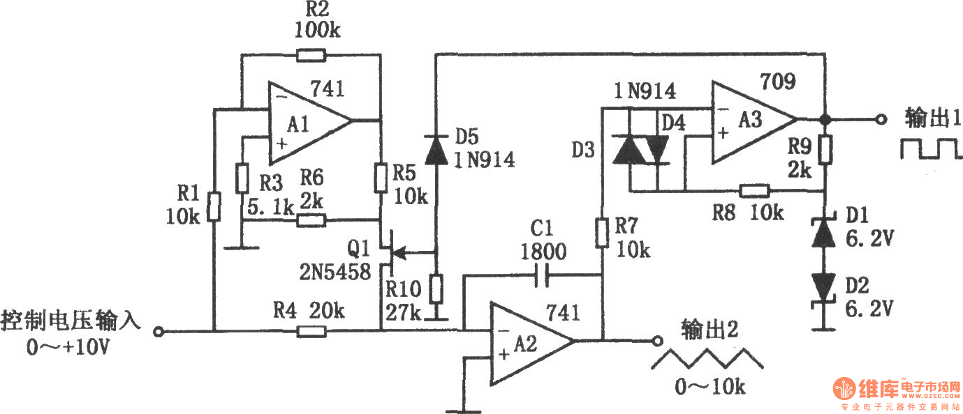
The voltage-controlled oscillator with triangular wave and square wave output is shown as the chart. The circuit is a controlled voltage-controlled oscillator. It has good stability and excellent linearity and a wide frequency range. The circuit has two output terminals, one is the square wave output, and the other one is the triangle wave output. In the figure, A1 is an inverter, A2 is an integrator, A3 is a comparator. The FET Q1 is used to transform integration direction. The reference voltage of comparator is provided by diode D1, D2, The comparing between the output of integrator and reference voltage make the square-wave output. Resistors R5, R6 are used to reduce the drain voltage of Q1 to ensure a large input signal Q1 being fully closed. Resistors R7, R8, and diodes D3, D4 A3 are used to prevent blocking. According to the value of marked components in the figure, the power supply is +15V, the transform coefficient is the 1kHz / V. The circuit has a linearity error less than ± 0.5% in the frequency range of 100:1.
Reprinted Url Of This Article:
http://www.seekic.com/circuit_diagram/Signal_Processing/Oscillator_Circuit/The_voltage_controlled_oscillator_with_triangular_wave_and_square_wave_output.html
Print this Page | Comments | Reading(3)

Article Categories
power supply circuit
Amplifier Circuit
Basic Circuit
LED and Light Circuit
Sensor Circuit
Signal Processing
Electrical Equipment Circuit
Control Circuit
Remote Control Circuit
A/D-D/A Converter Circuit
Audio Circuit
Measuring and Test Circuit
Communication Circuit
Computer-Related Circuit
555 Circuit
Automotive Circuit
Repairing Circuit
Code: