
Circuit Diagram
Index 1928
Static driver interface diagram
Published:2011/5/9 3:00:00 Author:Ecco | Keyword: Static driver , interface
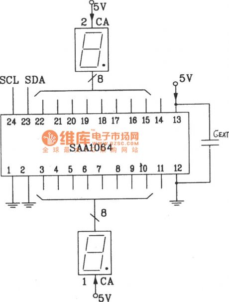
The static driver interface circuit diagram between SAA1064 serial I2C bus and LED display driver integrated circuit
In the quiescent mode, LED uses directly two 8-bit output port driver and it does not need to add an external driver. As the static drivers do not need to switch the scan circuit, the directly external capacitor side CEXT in the figure is connected to ground directly or Vcc. The ends of Vcc and VEE are added to decoupling capacitor, the general value is 0.01μF.
(View)
View full Circuit Diagram | Comments | Reading(585)
8-bit static LED display circuit diagram
Published:2011/5/9 2:46:00 Author:Ecco | Keyword: 8-bit, static, LED display
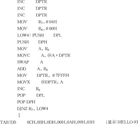
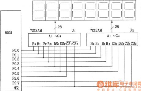
The 8-bit static LED display circuit composed of ICM7212AM 4-bit parallel display / decoder / driver (hardware decoding) The following is the programming process list of 8-character HELL0-98 . The 8 characters are stored in the beginning of the byte unit of table TAB in this program, R7 stores count data, R6 stores data temporarily.
(View)
View full Circuit Diagram | Comments | Reading(2005)
Short-circuit protection circuit with relay
Published:2011/5/9 4:13:00 Author:Rebekka | Keyword: Short-circuit protection , relay

View full Circuit Diagram | Comments | Reading(3465)
MP3 hardware schematic circuit diagram 1
Published:2011/5/9 3:59:00 Author:Rebekka | Keyword: MP3 hardware schematic

MP3 hardware schematic circuit diagram 1. (View)
View full Circuit Diagram | Comments | Reading(1597)
MP3 hardware schematic circuit diagram 2
Published:2011/5/9 3:59:00 Author:Rebekka | Keyword: MP3 hardware schematic

MP3 hardware schematic circuit diagram 2. (View)
View full Circuit Diagram | Comments | Reading(1438)
ZJ-200VA emergency power supply circuit diagram
Published:2011/5/9 4:06:00 Author:Rebekka | Keyword: emergency power supply

ZJ-200VA emergency power supply circuit diagram. (View)
View full Circuit Diagram | Comments | Reading(537)
TC89101P memory integrated circuit diagram
Published:2011/5/9 2:13:00 Author:Ecco | Keyword: memory, integrated circuit
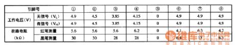
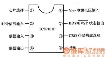
TC89101P is the memory integrated circuit produced by Toshiba, it is widely used in color television sets, air conditioning, audio and other system control circuit. 1. Features of functionsTC891O1P integrated circuit is mainly composed of memory matrix circuit, the selection circuit composed of CRG storage, the register circuit, data input / output interface circuit. 2. Pin functions and data TC89101P IC uses the package with 8 feet in the column, the pin functions are shown in Figure 1, the operating parameters are listed in Table 1.
(View)
View full Circuit Diagram | Comments | Reading(1195)
TOP223Y PWM monolithic integrated circuit diagram
Published:2011/5/9 1:34:00 Author:Ecco | Keyword: PWM , monolithic, integrated circuit


TOP223Y is th PWM monolithic switching power supply integrated circuit which is manufactured by the Power Company in the United States, it is widely used in switching power supply circuit of DVD, VCD, etc. DVD players, computers and monitors, air conditioner control system and various other household appliances. 1. pin functions and data TOP223Y IC uses separate three-pin package, the pin functions and data are listed in Table. T0P223Y integrated circuit pin functions and data 2. The typical application circuit The block diagram of TOP223Y integrated circuit and typical application circuit are shown as the chart. The block diagram and typical application circuit of TOP223Y IC
(View)
View full Circuit Diagram | Comments | Reading(2686)
high performance release in pairs circuit
Published:2011/5/7 13:16:00 Author:John | Keyword: high performance release in pairs circuit

The firgue shows the high performance release in pairs circuit. It is applicable for particularly strict release in pairs circuit. And it also can be used in general release in a receiver. Advantages for these circuits are high gain, excellent load capacity, good reliability and simple circuit. It also has a wide range for AGG. When used in pairs, consistency of amplitude frequency and phase frequency can be helpful to achieve very high targets. (View)
View full Circuit Diagram | Comments | Reading(591)
Frost Alarm Circuit
Published:2011/5/8 6:45:00 Author:Robert | Keyword: Frost, Alarm

In the natural disasters, the frost's damage to crops is very serious which can have a direct impact to crop yield.The frost alarm circuit introduced in this picture, can have the alarm sounds when the environmental temperature is lower than 1℃ to remind the farmers to prepare for anti-forst in time.The circuit's working principle is shown below.This frost alarm circuit is made up by power circuit, temperature monitoring control circuit and alarm circuit which is shown in the picture below. The power circuit is made up be battery GB, power switch S and electron-contact thermometers Q.The alarm circuit is made up by the sound effect integrated circuit IC, resistance R2, R3, transistor V and speaker BL.When the power switch S is connected, the alarm circuit is in alert mode. When the environmental temperature is higher than 1℃, the Q's electrical thermal control contactor is disconnected and the alarm circuit is not working and BL has no sound. When the environmental temperature decrease to 1℃ or less, the Q's electrical thermal contactor is connected to trigger the IC to work. The sound effect electrical signal from the IC's 3 foot is amplified by V to drive the BL to play the alarm sound.V uses 59013 or CW9561 type sound effect integrated circuit.
(View)
View full Circuit Diagram | Comments | Reading(789)
The No.1 Cluster and Warning Lamp Circuit of the Dong Feng Yue Da KIA-Qianlima Car
Published:2011/5/9 3:27:00 Author:Borg | Keyword: Cluster, Warning Lamp, Dong Feng Yue Da KIA-Qianlima

The No.1 Cluster and Warning Lamp Circuit of the Dong Feng Yue Da KIA-Qianlima Car (View)
View full Circuit Diagram | Comments | Reading(610)
The Central Locking System Circuit of the Dong Feng Yue Da KIA-Qianlima Car
Published:2011/5/9 3:18:00 Author:Borg | Keyword: Central Locking System, Dong Feng Yue Da KIA-Qianlima

The Central Locking System Circuit of the Dong Feng Yue Da KIA-Qianlima Car (View)
View full Circuit Diagram | Comments | Reading(1073)
The Starting System and Charging Circuit of the Dongfeng Yue Da KIA-Qianlima Car
Published:2011/5/9 3:16:00 Author:Borg | Keyword: Starting System, Charging, Dongfeng Yue Da KIA-Qianlima

The Starting System and Charging Circuit of the Dongfeng Yue Da KIA-Qianlima Car (View)
View full Circuit Diagram | Comments | Reading(784)
The Cluster and Warning Lamp Circuit of the Dong Feng Yue Da KIA-Qianlima Car
Published:2011/5/9 3:22:00 Author:Borg | Keyword: Cluster, Warning Lamp, Dong Feng Yue Da KIA-Qianlima

The Cluster and Warning Lamp Circuit of the Dong Feng Yue Da KIA-Qianlima Car (View)
View full Circuit Diagram | Comments | Reading(585)
The No.2 Cluster and Warning Lamp Circuit of the Dong Feng Yue Da KIA-Qianlima Car
Published:2011/5/9 3:24:00 Author:Borg | Keyword: Cluster, Warning Lamp, Dong Feng Yue Da KIA-Qianlima

The No.2 Cluster and Warning Lamp Circuit of the Dong Feng Yue Da KIA-Qianlima Car (View)
View full Circuit Diagram | Comments | Reading(584)
The Airbag System Circuit of the Dong Feng Yue Da KIA-Qianlima Car
Published:2011/5/9 3:31:00 Author:Borg | Keyword: Airbag System, Dong Feng Yue Da KIA-Qianlima

The Airbag System Circuit of the Dong Feng Yue Da KIA-Qianlima Car (View)
View full Circuit Diagram | Comments | Reading(611)
The No.2 Air-conditioning System Circuit of the Dong Feng Yue Da KIA-Qianlima Car
Published:2011/5/9 3:33:00 Author:Borg | Keyword: Air-conditioning System, Dong Feng Yue Da KIA-Qianlima

The Air-conditioning System Circuit of the Dong Feng Yue Da KIA-Qianlima Car (View)
View full Circuit Diagram | Comments | Reading(567)
The No.1 Air-conditioning System Circuit of the Dong Feng Yue Da KIA-Qianlima Car
Published:2011/5/9 3:35:00 Author:Borg | Keyword: Air-conditioning System, Dong Feng Yue Da KIA-Qianlima

The No.1 Air-conditioning System Circuit of the Dong Feng Yue Da KIA-Qianlima Car (View)
View full Circuit Diagram | Comments | Reading(629)
TTL state probe circuit
Published:2011/5/8 21:21:00 Author:Nicole | Keyword: TTL state probe
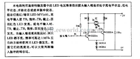
This circuit uses LED voltage drop of Schmitt trigger to indicate whether the probe input terminal is in high level state, low level state, open circuit state or string pulse state. The indicator light is red/green double LED MV5491. When it is high level input, TR1 is saturation, TR2 turns off, so red LED lights. When it is low level input, TR1 turns off, TR2 is saturation, so green LED lights. When the input terminal is high impedance, the two LEDs are all off. The square wave with 1MHz maximum frequency can make two LEDs light. According to their brightness ratio, it can judge the peak-to-trough ratio of input pulse. (View)
View full Circuit Diagram | Comments | Reading(362)
AC measuring circuit diagram
Published:2011/5/8 21:50:00 Author:Nicole | Keyword: AC measuring

The figures(a), (b) are as shown, they are AC measuring circuits. The 21(a) is a current measuring schematic diagram of magnetic balanced mode Hall device. If the magnetic field produced by the measured current IN is B1, then B1 will produce Hall voltage. If this voltage passes though A1, the produced current I2 is fed to feedback coil N2. When the Hall voltage UH=O, I2 reaches balance. Thus, INN1=fzN2, that is I2=(N1/N2)IN. If using resistance R to measure I2, then it can obtain a measured value which is in proportion to IN.
The figure21(b) is as shown, it is a current measurement practical circuit. Hall device adopts KH-400 of lnSb material. The constant current source circuit is composed of AD580, it provides H with 5mA control current. A1 is amplifier, A1's amplified voltage is changed to current by A2, it is lower than A2 output current, it is below 20mA, it is very tiny, so it should connect a current buffer amplifier which is composed of VT1 and VT2 to A2 output terminal. R1's voltage drop is shown on the meter, the shown value is the measured value. (View)
View full Circuit Diagram | Comments | Reading(4080)
| Pages:1928/2234 At 2019211922192319241925192619271928192919301931193219331934193519361937193819391940Under 20 |
Circuit Categories
power supply circuit
Amplifier Circuit
Basic Circuit
LED and Light Circuit
Sensor Circuit
Signal Processing
Electrical Equipment Circuit
Control Circuit
Remote Control Circuit
A/D-D/A Converter Circuit
Audio Circuit
Measuring and Test Circuit
Communication Circuit
Computer-Related Circuit
555 Circuit
Automotive Circuit
Repairing Circuit