Circuit Diagram
Index 1929
Shenyang JinBei SY6480 light bus technique parameter circuit diagram
Published:2011/5/9 3:33:00 Author:Nicole | Keyword: Shenyang JinBei, light bus, technique parameter
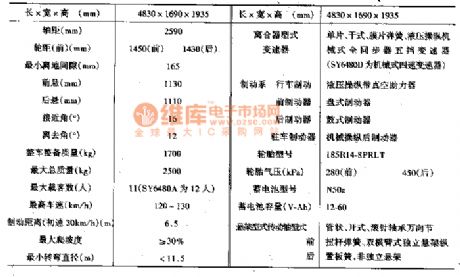
JinBei SY6480 series light bus has SY6480、5Y6480A、SY6480D、SY6480D1、5Y6480E、SY6480G and many models, the main performance parameter is shown in the table1.
(View)
View full Circuit Diagram | Comments | Reading(576)
LED luminescence circuit diagram
Published:2011/5/9 3:30:00 Author:Nicole | Keyword: LED, luminescence

The figure1 is a LED luminescence circuit. This circuit is widely used in factory's automatic production line, as optical switch, it can measure whether has block objects pass though. In the circuit, NE555 produces pulse current with small duty ratio, it can make LED shine. When VT2 cuts off, it charges, when VT1 turns on, it dischanges, then LED can obtain larger current. Because it adopts pulse luminescence mode, so it can reduce power consumption.
(View)
View full Circuit Diagram | Comments | Reading(594)
The Engine and Emission Control System of the Bluebird Car
Published:2011/5/9 3:07:00 Author:Borg | Keyword: Engine, Emission Control System

(A):Model A/T (L):Model L.H.D (M):Model M/T(R):Model R.H.D
(AA):Model A/T with A.S.C.D (AE): Model A/T without A.S.C.D
(CT):the model with a catalyst
(EC): the model without a catalyst
(HD):the model with a head-on display system
(EH): the model without a head-on display system
(SR):the model without a catalyst but with a SR20DE engine
The Engine and Emission Control System of the Bluebird Car (View)
View full Circuit Diagram | Comments | Reading(848)
The No.1 Automatic Transmission(AT) Circuit of the Bluebird Car
Published:2011/5/9 2:50:00 Author:Borg | Keyword: Automatic Transmission, Bluebird

The No.1 Automatic Transmission(AT) Circuit of the Bluebird Car (View)
View full Circuit Diagram | Comments | Reading(546)
The ABS Circuit of the Bluebird Car
Published:2011/5/9 2:44:00 Author:Borg | Keyword: ABS Circuit, Bluebird
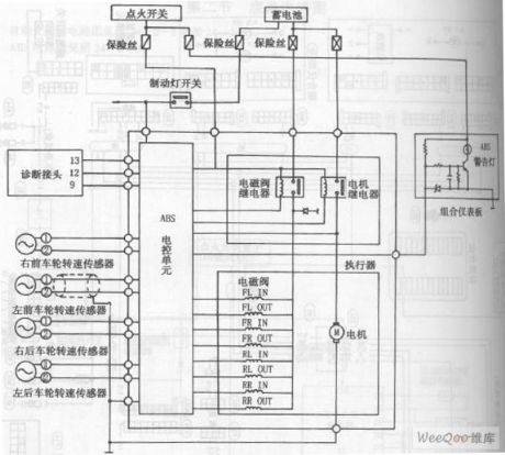
The ABS Circuit of the Bluebird Car (View)
View full Circuit Diagram | Comments | Reading(664)
The Charging System of the Bluebird Car
Published:2011/5/9 2:42:00 Author:Borg | Keyword: Charging System, Bluebird

The Charging System of the Bluebird Car (View)
View full Circuit Diagram | Comments | Reading(599)
The Starting System of the Bluebird Car
Published:2011/5/9 2:39:00 Author:Borg | Keyword: Starting System, Bluebird

The Starting System of the Blue Car (View)
View full Circuit Diagram | Comments | Reading(549)
The Rear Window Defogger Circuit of the Bluebird Car
Published:2011/5/9 2:32:00 Author:Borg | Keyword: Rear Window Defogger, Bluebird

The Rear Window Defogger Circuit of the Bluebird Car (View)
View full Circuit Diagram | Comments | Reading(1079)
MAX2l01-digital satellite receiving IF signal processing integrated circuit diagram
Published:2011/5/6 21:27:00 Author:Nicole | Keyword: digital satellite, receiving, IF signal processing

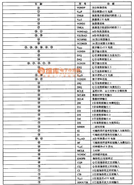
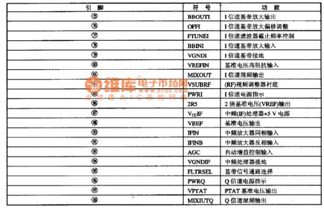
MAX2l01 is a digital satellite receiver special IF signal processing and A/D transformation single chip larger scale integrated circuit which is produced by MAXIM Company.
1, functions and features
MAX2l01 integrated circuit's sampling rate is 6OMb/S, it contains voltage controlled oscillator which is used for I/Q channel demodulator, orthogonal generator network, 16 prescaler which is used for phase locking loop oscillator, the changeable sampling rate programmable counter has the function of: signal detection and automatic baseband migration elimination. MAX2l01 receives narrow band medium frequency input singal, the center frequency is located between 400-700 MHz UHF frequency band. The typical application circuit of this integrated block is shown in the figure1.
The figure1 is the application circuit of MAX2l01 integrated block
2, pin function
MAX2l01 integrated circuit adopts 100-foot package, the pin function of this integrated circuit is shown in the table1.
The table1 is the pin function of MAX2l01 integrated circuit
(View)
View full Circuit Diagram | Comments | Reading(1534)
MAXl811-lithium battery charging integrated circuit diagram
Published:2011/5/6 21:42:00 Author:Nicole | Keyword: lithium battery, charging


MAXl811 is a lithium battery charging integrated circuit, the charger which is composed of this IC is widely used in MP3 player, digital camera and PDA and some portable instruments.
1. pin function and data
MAXl811 integrated circuit adopts 8-foot dual in-line package, the pin function and data of this integrated circuit is shown in the table1.
The table1 is the pin function and data of MAXl811 integrated circuit
2. typical application circuit
MAXl811 typical application circuit is shown in the figure1. The IC has two set terminals, when SELV is set to high level, the final charging voltage is 4.2V, when it is set to low level, the voltage is 4.1V. The other set terminal is SELI, when it is set to high level, the charging current is 500MA, when it is low level, the current is 100MA.
The figure1 is the typical application circuit of MAXl811 integrated block
(View)
View full Circuit Diagram | Comments | Reading(1096)
M64405FP-optical disk control microcomputer integrated circuit diagram
Published:2011/5/6 22:33:00 Author:Nicole | Keyword: optical disk control, microcomputer


M64405FP is a movement microcomputer integrated circuit with data process which is produced by Mitsubishi Corp and designed for DVD muti-chip decoding, this IC is used in all kinds of DVD players such as Panasonic series, Wanlida, TCL, Konka.
1. functions and features
M64405FP integrated circuit contains 8bit CPU and various ports, it can control all kinds of functions for movement, besides, it has synchronous detection, frame synchronization, sector same frequency, 8/16 demodulation, ECC and channel data process and DVD data process circuit. It can separate the repeated data-flow then make 8/16 demodulation and error correction, and it will be processed into 8bit parallel data decode circuit.
2. pin function and data
The pin function and data of M64405FP integrated circuit is shown in the table1, this IC adopts 4-line flat type package.
The normal waveform of M64405FP integrated circuit is shown in the figure1, it provides a reference when it is corrective maintenance.
(View)
View full Circuit Diagram | Comments | Reading(625)
The D.C Amplifier Circuit by Using Switches and Charging Capacitors
Published:2011/5/8 23:50:00 Author:Borg | Keyword: D.C Amplifier Circuit, Switches, Charging Capacitors

An Amplifier Circuit without any Amplifier:As shown is the amplification circuit without any amplifiers.Thisis a series amplifier circuit formed by switches and charging capacitors,which has a steady power of 8 and requires 8 fixed periods as an average time of input signal. The process ofthe circuit is that a sample clock drived devider IC3(74HC393) of 400Hz output to choose a capacitor to cross the analog switches IC1 and IC2 forming a charging circuit, and then IC2 will couple the input signals to each capacitor, while IC2 is to provide a corresponding current for every capaticor to come back to the circuit. When six contacts of IC1 and IC2 (1NH)are under low electric levels, these analog switches will be turned off. Under this condition, the total voltage on the 8 series capatitors is 8 times ashighasaverage input voltage. If the switches are effective, the output voltage can be put on aprobeor amplifierof difference input. Moreover,this circuit has a lowrequirement on the frequecy of the clock. (View)
View full Circuit Diagram | Comments | Reading(426)
M58480P-remote control emission integrated circuit diagram
Published:2011/5/6 22:44:00 Author:Nicole | Keyword: remote control, emission


M58480P is a remote control emission integrated circuit which is produced by Mitsubishi Corp, it is used as infrared singal process in the system.
1. internal circuit block diagram and pin function
M58480P integrated circuit contains key instruction singal compiling, decoding circuit, path instruction decode circuit, the internal circuit block diagram and pin function of this integrated block is shown in the figure1.
2. practical data
M58480P's all kinds of pin working voltage which is used in remote control transmitter is shown in the table1.
The figure1 is the internal circuit block diagram and pin function of M58480P integrated block
The table1 is the M58480P's all kinds of pin working voltage which is used in remote control transmitter
(View)
View full Circuit Diagram | Comments | Reading(827)
M51131L-audio and microphone sound control integrated circuit diagram
Published:2011/5/8 22:03:00 Author:Nicole | Keyword: audio, microphone, sound control


M51131L is a audio and microphone sound control integrated circuit which is produced by Mitsubishi Corp, it is mainly used in TV audio, karaoke audio system.
1. M51131L typical application circuit
The typical application circuit of M51131L integrated block is shown in the figure 1-1. This IC adopts single row 14-foot in-line package, the pin function and data of this integrated circuit is shown in the table1.
The table is the pin function and data of M51131L integrated circuit
The figure1 is the typical application circuit of M51131L integrated block
(View)
View full Circuit Diagram | Comments | Reading(2385)
M37221M6-single chip microcomputer control integrated circuit diagram
Published:2011/5/8 22:18:00 Author:Nicole | Keyword: single chip, microcomputer control


M37221M6 is a single chip microcomputer control integrated circuit which is produced by Mitsubishi Corp, it is specially used in TCL series large screen color television, such as TCL2911DZ、3811DZ、3416DI, the model is TCL一Mll in the TCL series.
1. functions and features
M37221M6 integrated circuit contains frequency band control, I square meter C data and clock bus, key switch comiling and decoding, character display, AV/TV transfer control, system switching control, tone control, tune voltage control, opportunity-awaiting/start-up control, master clock crystal oscillator, character display clock circuit and other control circuits.
2. pin function and data
M37221M6 integrated circuit adopts 42-foot dual in-line package, it is applied to TCL2911DZ series color television, the in function and data of this integrated circuit is shown in the table1.
The table is the pin function and data of M37221M6 integrated circuit
(View)
View full Circuit Diagram | Comments | Reading(2585)
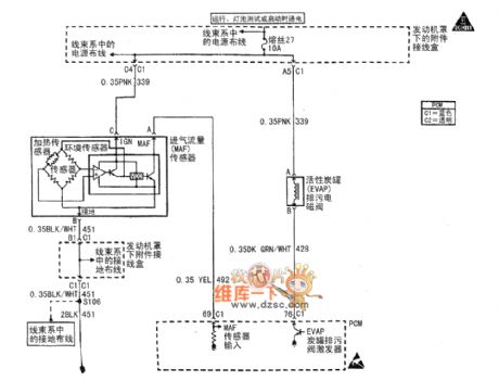
Buick Century car motor circuit diagram(7)
Published:2011/5/9 3:17:00 Author:Nicole | Keyword: Buick Century, car, motor
View full Circuit Diagram | Comments | Reading(452)
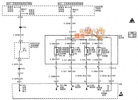
Buick Century car motor circuit diagram(11)
Published:2011/5/9 3:16:00 Author:Nicole | Keyword: Buick Century, car, motor
View full Circuit Diagram | Comments | Reading(423)
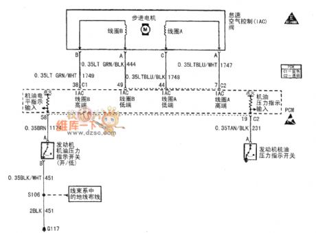
Buick Century car motor circuit diagram(8)
Published:2011/5/9 3:16:00 Author:Nicole | Keyword: Buick Century, car, motor
View full Circuit Diagram | Comments | Reading(458)
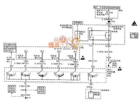
Buick Century car motor circuit diagram(10)
Published:2011/5/9 3:16:00 Author:Nicole | Keyword: Buick Century, car, motor
View full Circuit Diagram | Comments | Reading(438)
The Amplifier Circuit of Adjustable Gain by Using Digipots
Published:2011/5/8 23:38:00 Author:Borg | Keyword: Amplifier Circuit, Adjustable Gain, Digipot


By using the dual digital potentiometer, the amplifer circuit of adjustable gain can be designed as follows(R2 means singal digital POT,and R4 means the consistent resistence), so the resistences of the intergrated operational non-inverting and inverting points always remain the same, therefore , not only the CMRR can be kept quite high, but also the temperature-excursion is hold back.
(View)
View full Circuit Diagram | Comments | Reading(461)
| Pages:1929/2234 At 2019211922192319241925192619271928192919301931193219331934193519361937193819391940Under 20 |
Circuit Categories
power supply circuit
Amplifier Circuit
Basic Circuit
LED and Light Circuit
Sensor Circuit
Signal Processing
Electrical Equipment Circuit
Control Circuit
Remote Control Circuit
A/D-D/A Converter Circuit
Audio Circuit
Measuring and Test Circuit
Communication Circuit
Computer-Related Circuit
555 Circuit
Automotive Circuit
Repairing Circuit
