
Circuit Diagram
Index 1925
MN187-681 Single-chip Microcomputer Integrated Circuit
Published:2011/5/8 22:09:00 Author:Sharon | Keyword: Single-chip, Microcomputer, Integrated


MN187-681 is a single-chip microcomputer integrated circuit produced by Panasonic company, widely used in the large-screen color TV assembled by Panasonic movement. 1. FeaturesMN187-681 IC's within is mainly composed of clock oscillation circuit by the reset control circuit, I2C-bus circuit, the central micro-processing circuit, the key instruction decoding circuit, the character display circuit, remote command signal processing circuit, mode switching control circuit, standby / on control circuit, the audio signal conditioning circuits and other control functions and auxiliary functions circuit. 2. Pin functions and data MN187-681 IC is with 42 pins dual in-line package. the internal circuit block diagram and pin functions and signal flow of the bow are shown in the figure, and the pin code and data table are listed in the letter.
(View)
View full Circuit Diagram | Comments | Reading(614)
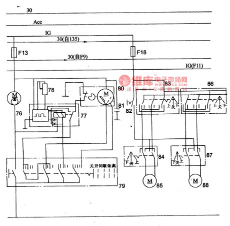
The Wiper/Washer and Power Kong Principle Circuit of MAZDA 929
Published:2011/5/9 11:15:00 Author:Borg | Keyword: Wiper/Washer, Power Kong
View full Circuit Diagram | Comments | Reading(619)
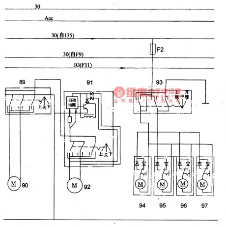
The Power Window and Control Door Lock Principle Circuit of MAZDA 929
Published:2011/5/9 11:11:00 Author:Borg | Keyword: Power Window, Control Door Lock, MAZDA 929
View full Circuit Diagram | Comments | Reading(1188)
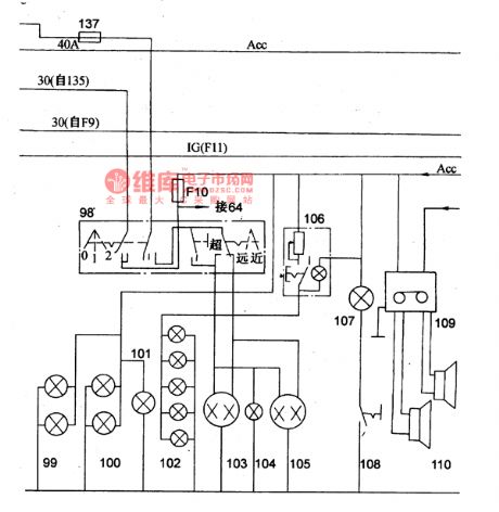
The Lighting, Head Lamps and Radio Principle Circuit of the Mazda 929 Car
Published:2011/5/9 8:27:00 Author:Borg | Keyword: Lighting, Head Lamps, Principle Circuit
View full Circuit Diagram | Comments | Reading(637)
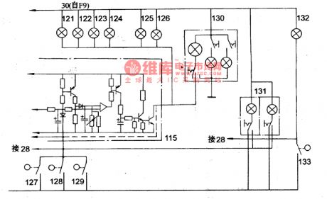
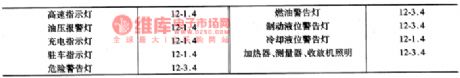
The Automatic Antenna,Door and Warning Lamp Circuit of the Mazda 929 Car
Published:2011/5/9 11:05:00 Author:Borg | Keyword: Automatic Antenna, Warning Lamp
View full Circuit Diagram | Comments | Reading(589)
The Interior Light,Step Lamp and Trunk Circuit of the Mazda 929 Car
Published:2011/5/9 10:59:00 Author:Borg | Keyword: Interior Light, Step Lamp, Trunk
View full Circuit Diagram | Comments | Reading(683)
Object Motion Direction Identification Circuit
Published:2011/5/9 2:42:00 Author:Sharon | Keyword: Object Motion, Direction Identification

Place two objects of similar resistance and performance on the same side of the object motion path, with an appropriate distance from each other. The relative position of the other side is installed two light sources respectively, so that objects between the light source and photosensitive resistancemove move in direct line. The circuit in the figure can judge the direction of the moving objects. The circuit is formed by two parts: bridge and the polarity discrimination. Rs1, Rs2, R1, R2 and Rw form the bridge, E0 provides power supply and A, B-side output. Before measuring, make Rs1 and Rs2 in the same shade or light, adjust Rw, so that the bridge is balanced. UAB = 0V. When measuring, when the object move from the bottom to up, Rs2 is the first to be shaded, resistance increases, Rs1 is in light, resistance is less, and bridge is unbalanced. UA> UB, UAB> 0V, the VT1, VT2 is ended, VT3, VT4 get through, relay J1maintains the off state, and J2 pulls. When the object continues to move upward to the Rl position, the opposite, J1 pulls, J2 opens. If the object conducts the top-down movement, contrary to the above, J1 is prior J2 to pull. Thus, J1 and J2's pull sequences can determine direction of objects movement, and provide the corresponding switching control signal output. (View)
View full Circuit Diagram | Comments | Reading(816)
The Intergrated Circuit of HICIO15 Switch Control
Published:2011/5/9 8:33:00 Author:Borg | Keyword: Intergrated Circuit, Switch Control, HICIO15
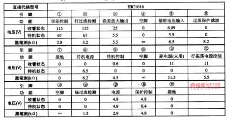
Table 1-1 the pinning functions and data of HIC1015 intergrated circuit (View)
View full Circuit Diagram | Comments | Reading(506)
The Main Technology Parameter Circuit of Mazda Battery
Published:2011/5/9 8:22:00 Author:Borg | Keyword: Technology Parameter, Battery
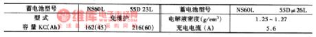
(2)main specifications of batteries
(View)
View full Circuit Diagram | Comments | Reading(540)
The Main Technology Parameter Circuit of the AC Motor of Mazda
Published:2011/5/9 8:19:00 Author:Borg | Keyword: Technology Parameter, AC Motor
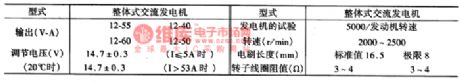
(3) main specifications of AC generators
(View)
View full Circuit Diagram | Comments | Reading(549)
The Main Technology Parameter Circuit of Mazda Motor
Published:2011/5/9 8:12:00 Author:Borg | Keyword: Technology Parameter, Mazda
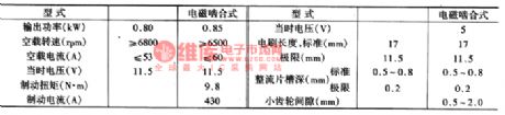
(4)main specifications of starting motors(as shown in table 3.)
(View)
View full Circuit Diagram | Comments | Reading(559)
Beam Blocking Alarm Circuit
Published:2011/5/9 2:59:00 Author:Sharon | Keyword: Beam Blocking, Alarm

As shown in the figure, when the photosensitive resistor R4 is irradiated, the resistance is low, thus, transistor VT1 and one-way thyristor SCR are closed; when the beam is blocked, the base voltage of VT1 increase, VT1, SCR is conducted, and audible alarm buzzer BZ is energized. S1 is the reset switch. Press S1, the circuit stops the alarm. (View)
View full Circuit Diagram | Comments | Reading(859)
The Bulb Power Circuit of Mazda
Published:2011/5/9 7:11:00 Author:Borg | Keyword: Bulb Power, Mazda
(6) Bulb Power(as shown in the figure)
(View)
View full Circuit Diagram | Comments | Reading(569)
The Element Circuit of the Nanjing NAVECO Light Vehicles
Published:2011/5/9 10:53:00 Author:Borg | Keyword: Element, NAVECO, Light Vehicles
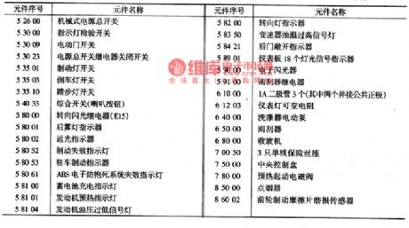
The Element Sequential List of the Circuit Diagram
(View)
View full Circuit Diagram | Comments | Reading(448)
A Precision bright light control circuit
Published:2011/5/9 3:07:00 Author:Sharon | Keyword: Precision, bright, light control

The circuit shown is a precision bright light control circuit. Its work will not be affected by power supply voltage and ambient temperature. Resistors R1, R2, R6 and the photosensitive resistor R5 constitute the two bridge arms of Wheatstone bridge. (View)
View full Circuit Diagram | Comments | Reading(682)
Precision Dimming Light Control Circuit
Published:2011/5/9 3:18:00 Author:Sharon | Keyword: Precision, Dimming Light Control

Precision dimming light control circuit is as shown in the figure. Since the introduction of R5 has brought a small amount of positive feedback, with the change of the light, circuit action will be slightly delayed in order to avoid the relay's frequent jitter at the time ofthe light intensity is in critical state.
(View)
View full Circuit Diagram | Comments | Reading(919)
Temperature control circuit of the fan
Published:2011/5/9 18:44:00 Author:TaoXi | Keyword: Temperature control, fan
The Temperature control circuit of the fan: (View)
View full Circuit Diagram | Comments | Reading(605)
Time-setting and time-saving switch circuit
Published:2011/5/9 3:38:00 Author:Sharon | Keyword: Time-setting, time-saving, switch

Nowadays, the door and light are mostly controlled by manual switches. Frequent forgetting to turn on or off the lights result in inconvenience and energy waste. If we can increase the light control and timing functions of them, automation and energy-saving effect can be achieved. Ready-made light control timer ICMG2001B is suggested here. It is a cheap 1h ~ 36h9 block optional timing and delay IC. The external circuit is simple with a light-driven port, photoresistors interface, low-cost 32.768kHz crystal as clock source, and the time accuracy is up to one hundred thousandth and it's very suitable for making lamps automatic control circuit. According to actual situation, choose the basic 4 block time (1h, 3h, 5h, 8h) plus one switching function to form a 5-speed light control timer circuit, and then install them into the normal 5-speed surface shell to make a 5 block light control timer switch so as to control the door lights or street lamps. Circuit is as shown in the figure.
(View)
View full Circuit Diagram | Comments | Reading(800)
Colorimeter and Concentration Meter Circuit
Published:2011/5/9 2:12:00 Author:Sharon | Keyword: Colorimeter, Concentration Meter

As the circuit shows, when the sample is inserted, the photosensitive resistor will transform its received light intensity into electrical signals according to the concentration or density of sample size, and drive display instrument through the amplifier. The measuring instrument is generally used for the concentration of emulsion, gray film density and transmittance measurements. Amplifier and display instruments can be selected according to specific needs. RP regulation can be detected by different samples.
(View)
View full Circuit Diagram | Comments | Reading(1309)
PQ3RD13 3.3V four-terminal voltage regulator integrated circuit diagram
Published:2011/5/9 3:12:00 Author:Ecco | Keyword: 3.3V, four-terminal , voltage regulator, integrated circuit

PQ3RD13 is the 3.3V controlled voltage regulator four-terminal integrated circuit, which is widely used as voltage regulator in DVD players, color, computer monitors, printers, fax machines, and a variety of household electrical power supply.1. Features of functionsPQ3RD13 IC includes 3V power supply circuit, power supply circuit on / off control circuit, and other ancillary functions circuit. 2. Pin functions and data PQ3RD13 IC is packaged with 4 feet in a single row, the pin functions and data are listed in Table. 3. The typical application circuit The power typical application circuit composed of PQ3RD13 integrated circuit is shown as Figure.
(View)
View full Circuit Diagram | Comments | Reading(839)
| Pages:1925/2234 At 2019211922192319241925192619271928192919301931193219331934193519361937193819391940Under 20 |
Circuit Categories
power supply circuit
Amplifier Circuit
Basic Circuit
LED and Light Circuit
Sensor Circuit
Signal Processing
Electrical Equipment Circuit
Control Circuit
Remote Control Circuit
A/D-D/A Converter Circuit
Audio Circuit
Measuring and Test Circuit
Communication Circuit
Computer-Related Circuit
555 Circuit
Automotive Circuit
Repairing Circuit