
Circuit Diagram
Index 1941
Sawtooth Wave Generating Circuit
Published:2011/5/6 6:39:00 Author:Sue | Keyword: Sawtooth Wave, Generating

Sawtooth wave generating circuit used in output of Television electric field. (View)
View full Circuit Diagram | Comments | Reading(446)
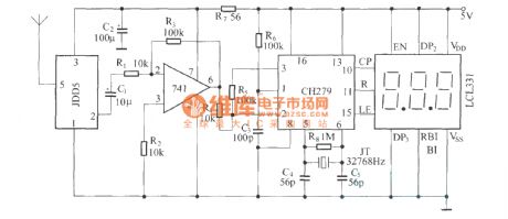
Time Base Circuit Composed of 32768Hz Crystal SJT Generating 60Hz Signal
Published:2011/5/6 22:13:00 Author:Sue | Keyword: Time Base, 32768Hz, Crystal SJT, 60Hz Signal


Waveform:
(View)
View full Circuit Diagram | Comments | Reading(808)
555 Monostable Trigger Circuit
Published:2011/5/6 2:23:00 Author:Sue | Keyword: Monostable, Trigger

(a) Circuit
(b) Relation between output pulse width and capacitance (View)
View full Circuit Diagram | Comments | Reading(718)
Timing Nicel Cadmium Battery Charger(CD4060) Circuit
Published:2011/5/6 5:50:00 Author:Sue | Keyword: Timing, Nicel Cadmium, Battery, Charger
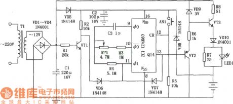
View full Circuit Diagram | Comments | Reading(2499)
Nicel Cadmium Battery Charger Circuit Composed of CD4541
Published:2011/5/6 5:49:00 Author:Sue | Keyword: Nicel Cadmium, Battery, Charger
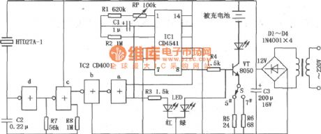
View full Circuit Diagram | Comments | Reading(1282)
Nicel Cadmium Battery Charger(LM393) Circuit
Published:2011/5/6 5:47:00 Author:Sue | Keyword: Nicel Cadmium, Battery, Charger
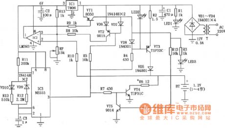
View full Circuit Diagram | Comments | Reading(3604)
Mobile Phone Battery Constant Current Charger(TNY254P +6.7V、0.56A) Circuit
Published:2011/5/6 5:45:00 Author:Sue | Keyword: Mobile Phone, Battery, Constant Current, Charger
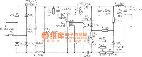
View full Circuit Diagram | Comments | Reading(785)
Current-limiting Step-down Resistance and Capacitance Storage Battery Charger Circuit
Published:2011/5/6 5:40:00 Author:Sue | Keyword: Current-limiting, Step-down, Resistance, Capacitance, Storage Battery, Charger
View full Circuit Diagram | Comments | Reading(581)
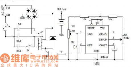
Large Range Variable Duty Ratio Square Wave Generator Circuit
Published:2011/5/6 2:38:00 Author:Sue | Keyword: Large Range, Variable, Duty Ratio, Square Wave, Generator


As seen in the figure, 555 and R1,R2,RP1,D1,D2,C1 constitute a astable multivibrator. D1 and D2 serve as guide tubes for charge/discharge circuit.
We can se from the formula above that, no matter how RP1 varies, it has no influence on oscillation period T. The oscillation frequency shown in the figure is about 20Hz. (View)
View full Circuit Diagram | Comments | Reading(959)
Differential Triggering 555 Circuit
Published:2011/5/6 2:25:00 Author:Sue | Keyword: Differential, Triggering

View full Circuit Diagram | Comments | Reading(654)
zhongyi BCD-215 fridge circuit diagram
Published:2011/5/7 21:25:00 Author: | Keyword: fridge, circuit

View full Circuit Diagram | Comments | Reading(587)
Changan Ford Mondeo motor-driven door and window circuit diagram
Published:2011/5/6 3:40:00 Author:muriel | Keyword: Changan Ford Mondeo , motor-driven door and window
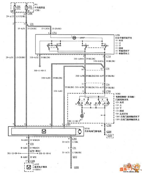
Changan Ford Mondeo motor-driven door and window circuit diagram is as shown
(View)
View full Circuit Diagram | Comments | Reading(1444)
Digital remote thermometer(FDD5/JDD5) circuit diagram
Published:2011/4/8 3:02:00 Author:Rebekka | Keyword: Digital remote thermometer
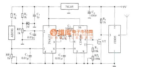
Transmitter circuit:
Temperature detection circuit is composed of integrated temperature sensor AD590. It can convert temperature changes into output current changes. The output current of AD590 should be proportional to measured temperature. As the temperature increases, the output current 1μA / K a constant rate should increase. When the output current pass RP2, it will form into voltage drop on its upper. After being amplified by the voltage amplifier, the voltage will be the voltage of frequency converter.
(View)
View full Circuit Diagram | Comments | Reading(2269)
Using PT2128/PT2268 function remote control fan circuit diagram
Published:2011/4/8 3:02:00 Author:Rebekka | Keyword: function remote control , fan circuit


PT2268 remote control encoder transmitter circuit:
PT2128 Lantern Musicvariable speed fan control circuit:
(View)
View full Circuit Diagram | Comments | Reading(3061)
Air-conditioning control panel circuit including an main control board and remote control PIC16C54
Published:2011/4/8 3:01:00 Author:Rebekka | Keyword: Air-conditioning control panel, control board , remote control

View full Circuit Diagram | Comments | Reading(4176)
Simple audio power meter circuit diagram composed of LM3915
Published:2011/5/6 3:26:00 Author:Ecco | Keyword: Simple , audio power meter

Simple audio power meter circuit diagram composed of LM3915 Note: If the internal resistance of speaker is 4Ω, Rx takeS 10kΩ; the internal resistance is 8Ω, Rx takes 18kΩ, internal resistance is 16Ω, Rx is 30kΩ The more perfect way of this IC showing AC signal amplitude is using half-wave AC signal converter to change the DC signal, and then the DC signal is sent to the IC's input. (View)
View full Circuit Diagram | Comments | Reading(2451)
The structure circuit diagram of chip diode
Published:2011/5/6 3:27:00 Author:Ecco | Keyword: structure circuit, chip diode

The structure circuit diagram of chip diode is shown as the chart.
The chip diode has many different types such as the rectifier diode, varactor diode, fast recovery diode, switching diode, zener diode, light emitting diode and transient voltage suppression diode. Most models of the chip diodes use the model of leading diode, some manufacturers also have their own requiring model, There is no uniform requirements.
(View)
View full Circuit Diagram | Comments | Reading(1806)
The typical application circuit diagram of LD7208 police car turning ASIC
Published:2011/5/6 3:25:00 Author:Ecco | Keyword: typical application circuit, police car, turning, ASIC

The typical application circuit of LD7208 police car turning ASIC
The main function of the circuit: When normal operation, the lights are in good condition, lights and the monitoring lights of bridge flash at the same time, the flash frequency is 80 times / min. Once the lamp is damaged, then the flashing frequency of monitoring lights will increase twice to show alarm. (View)
View full Circuit Diagram | Comments | Reading(1032)
A Video Games Circuit Diagram
Published:2011/5/6 3:26:00 Author:Ecco | Keyword: Video Games

IC1 ~ IC4 are four pairs of CD4051 4-bit shift register; D1 ~ D4 use a CD4011 2 input NAND gate. Color tri-color LED is 2EF302. (View)
View full Circuit Diagram | Comments | Reading(1284)
The clock circuit diagram for racing
Published:2011/5/6 3:25:00 Author:Ecco | Keyword: clock circuit, racing

The chart shows the clock for the competition, which is assembled with 555 circuit, with the features of novel circuit, reliable performance, easy making, intuitive interesting. 555 circuit has two categories of bipolar circuit (TTL) and complementary metal oxide semiconductor-type (CMOS) integrated circuit. It is a very broad application IC with only a small amount of external components, it is very easy to form a single stable, bistable, non-stable circuit. The selection of components: IC uses bipolar CD555 time base circuit. VT selects 3DG6 transistor. VD1 ~ VD3 chooses Φ5mm. The clock uses analog quartz.
(View)
View full Circuit Diagram | Comments | Reading(1199)
| Pages:1941/2234 At 2019411942194319441945194619471948194919501951195219531954195519561957195819591960Under 20 |
Circuit Categories
power supply circuit
Amplifier Circuit
Basic Circuit
LED and Light Circuit
Sensor Circuit
Signal Processing
Electrical Equipment Circuit
Control Circuit
Remote Control Circuit
A/D-D/A Converter Circuit
Audio Circuit
Measuring and Test Circuit
Communication Circuit
Computer-Related Circuit
555 Circuit
Automotive Circuit
Repairing Circuit