
Circuit Diagram
Index 1949
UM91215A/C microcomputer single chip dialing integrated circuit diagram
Published:2011/5/5 8:46:00 Author:Nicole | Keyword: microcomputer, single chip dialing

UM91215A, UM91215C are microcomputer single chip dialing integrated circuit, as dialing circuit, it is used in communication equipment.
UM91215A adopts 16-foot dual in-line package, UM91215C adopts 18-foot dual in-line package, the later ① foot is hands free control singal output terminal, (18) foot is hands free control singal input terminal. UM91215A integrated circuit's pin function and data are shown in the excel 1-1.
(View)
View full Circuit Diagram | Comments | Reading(880)
Beijing Cherokee light off-road vehicle fusing color marker circuit diagram
Published:2011/5/5 9:59:00 Author:Rebekka | Keyword: Beijing Cherokee light off-road vehicle, fusing color marker
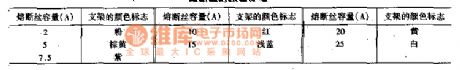
View full Circuit Diagram | Comments | Reading(384)
Beijing Cherokee 4.0L engine electronic control system main relay and computer wiring circuit diagram
Published:2011/5/5 6:31:00 Author:Rebekka | Keyword: Beijing Cherokee , electronic control system, main relay and computer wiring

Beijing Cherokee 4.0L engine electronic control system main relay and computer wiring circuit diagram. (View)
View full Circuit Diagram | Comments | Reading(481)
Beijing Cherokee 4.0L engine electronic control system ignition coils ignition coil relay and computer wiring circuit diagram
Published:2011/5/5 6:27:00 Author:Rebekka | Keyword: Beijing Cherokee 4.0L engine , electronic control system , ignition coils

Beijing Cherokee 4.0L engine electronic control system ignition coils ignition coil relay and computer wiring circuit diagram. (View)
View full Circuit Diagram | Comments | Reading(733)
Beijing Cherokee 4.0L engine electronic control system sensor and computer wiring circuit diagram
Published:2011/5/5 6:31:00 Author:Rebekka | Keyword: Beijing Cherokee 4.0L engine, electronic control system sensor , computer wiring
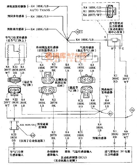
Beijing Cherokee 4.0L engine electronic control system sensor and computer wiring circuit diagram. (View)
View full Circuit Diagram | Comments | Reading(432)
Smoke detection alarm circuit diagram
Published:2011/5/5 20:32:00 Author:Ecco | Keyword: Smoke , detection , alarm circuit

The smoke detection alarm circuit composed of MC14468 Ionic smoke detection alarm integrated circuit is shown as the chart. The device uses 9V laminated battery. RT and CT are respectively oscillation resistor and oscillation capacitor. LED is Light-emitting diode, R1 is the current limit resistor. BZ is the piezoelectric ceramic buzzer, which consists of three electrodes, namely B pole, F pole and S pole. Ion source is americium 241 (Am241), the radioactive intensity is as low as 0.8Ci (or 0.8 micro-Curie), and it will not cause harm to humans and pollute the environment. Ion source is installed at the top of the ion chamber. R4 and R5 are the partial pressure resistors. SB is self-test button. The source connects to +9 V voltage under normal state, when it is connected to SB, the voltage is +4.5 V, then it can simulate the case of detecting smoke. MC14468 can be connected to other test unit circuits through pin 2. (View)
View full Circuit Diagram | Comments | Reading(1359)
Beijing Cherokee 4.0L engine control system sensor and computer wiring circuit diagram
Published:2011/5/5 6:23:00 Author:Rebekka | Keyword: Beijing Cherokee 4.0L engine control system sensor , computer wiring
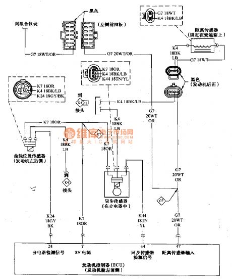
Beijing Cherokee 4.0L engine control system sensor and computer wiring circuit diagram. (View)
View full Circuit Diagram | Comments | Reading(521)
Chip diode usual encapsulation and shape dimension circuit diagram
Published:2011/5/5 21:48:00 Author:Ecco | Keyword: Chip diode, usual , encapsulation , shape , dimension


Chip diode usual encapsulation and shape dimension circuit diagram is shown as the chart.
The table lists the ususal package and shape dimensions for reference.
(View)
View full Circuit Diagram | Comments | Reading(553)
EIA-422-A input protection circuit diagram
Published:2011/5/5 9:31:00 Author:Rebekka | Keyword: input protection

The figure shows two signal lines transmit digital signal EIA-422-A input protection circuit. Resistor R and diode VD1 ~ VD2 are used for protection. (View)
View full Circuit Diagram | Comments | Reading(1318)
Memory integrated circuit diagram
Published:2011/5/5 20:49:00 Author:Ecco | Keyword: Memory, integrated circuit


PCF8582P is the memory integrated circuit produced by Philips, it is widely used in color television sets, audio, DVD players, air-conditioning system control circuit. 1. Features of functionIt is composed of some of the subsidiary function circuit. 2. Pin functions and data PCF8582P IC is packaged with 8-pin in double rows, the pin functions are shown in the figure, the operating voltage is listed in Table. PCF8582P IC pin function PCF8582P integrated circuit working voltage
(View)
View full Circuit Diagram | Comments | Reading(704)
SMB820OCP FSK decoder integrated circuit diagram
Published:2011/5/5 22:04:00 Author:Rebekka | Keyword: FSK decoder, integrated circuit

SMB820OCP is a frequency shift keying decoder integrated circuit. It is widely used for receiving and displaying the calling number of switch equipment and information products (such as Caller ID cordless / corded telephone, etc.). 1. Pin functions and data.SMB820OCP integrated circuit uses double row 16-pin IC DIP packages, the pin functions and data are listed in table 1.
Table 1 SMB822OCP IC pin functions and data 2. Similar IC The pinouts and functions of SMB820OCP and HR220, MCl45447P are basically the same and the three can be directly used interchangeably. (View)
View full Circuit Diagram | Comments | Reading(700)
Beijing Cherokee light off-road vehicle circuit wiring connector code position and shape circuit diagram
Published:2011/5/5 6:43:00 Author:Rebekka | Keyword: Beijing Cherokee light off-road vehicle, circuit wiring connector code
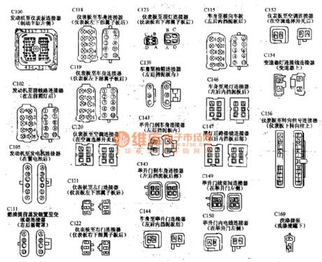
Beijing Cherokee light off-road vehicle circuit wiring connector code position and shape circuit diagram. (View)
View full Circuit Diagram | Comments | Reading(434)
0-1 hours of power supply timing AC power supply circuit diagram
Published:2011/5/5 22:08:00 Author:Rebekka | Keyword: power supply timing AC power supply

View full Circuit Diagram | Comments | Reading(412)
Two-color LED internal circuit diagram
Published:2011/5/5 7:53:00 Author:Rebekka | Keyword: Two-color LED internal circuit

LED is small, cheap, long life, high reliability. It is often used in power-off state display and monitoring circuit. The most convenient two-color LED. The face of it looks like an ordinary LED, but it has three pins. Two-color LED's internal circuit is shown as below. The two LED are connected. There are common cathode, common anode and series because of different connection. (View)
View full Circuit Diagram | Comments | Reading(2198)
Five functions ultrared remote control receiving circuit diagram
Published:2011/5/5 21:26:00 Author:Nicole | Keyword: function, ultrared remote control, receiving

The figure1 is a five functions ultrared remote control receiving circuit. In the figure 1(a), SDA205 is ultrared remote control receiving decoding integrated circuit, after it receives a series of instructions which is sent by transmitting circuit, it will start to work. If the instructions are program advances P+ and program advances P- , then the ring counter has 16 channels selection, it outputs A, B, C, D. If the instruction is simulation+ and simulation - it can be used for voice controlling(output UOL). The fifth function is ON/OFF , when it is off, the device is in standby state, PC terminal outputs high level, TV's channel transformation is no effect. If it is changed into the circuit as shown in the figure1(b), it still can be remote controlled, swtich S1 is pressed, then VT2 turns on, standby output terminal ON/OFF is enforced into low level. When input PC is high level, for the ring counter, it is program advances P+ . In standby action, PC output is high level, because it is connected to diode VD1, VT2 turns off, so it is no influence on circuit. K1 is standby relay.
(View)
View full Circuit Diagram | Comments | Reading(833)
TDA7056 integrated block typical application circuit
Published:2011/5/5 21:00:00 Author:TaoXi | Keyword: integrated block, typical application
The TDA4856 is designed as one kind of line&field scanning front class front-end B+ power control circuit, and it can be used in a variety of computer color monitor applications. The pin functions and data is as shown in table 14--18
Table 14--18 The pin functions and data of the TDA4856
(View)
View full Circuit Diagram | Comments | Reading(8741)
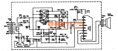
170W power amplifier circuit composed of the LM4561 and LM4562
Published:2011/5/5 20:55:00 Author:TaoXi | Keyword: 170W, power amplifier

The 170W power amplifier circuit with 4Ω load is as shown in figure (a);
LM4651 is the front circuit of the D class amplifier, it is in the 28-pin DIP package, and the internal equivalent circuit is as shown in figure (c); (View)
View full Circuit Diagram | Comments | Reading(2172)
VCA electronic attenuation circuit
Published:2011/5/5 20:50:00 Author:TaoXi | Keyword: electronic attenuation

The voltage-controlled amplifier's (VCA) gain is controlled by the voltage, this device can be used in the applications of radio tuner control, automatic audio control, instrumentation preamplifier control, computer acquisition system control, also it can be used as the pulse modulator, the phase detector, the wave filter and the high-precision multiplier.etc.
Circuit of the TD4000 is as shown in figure (a);
The VCA electronic attenuation circuit is shown in the figure (b), it is an application. When the VCA is used as the electronic attenuator, it's features are better than the mechanical attenuator of the chinese broadcasting system, because it does not has the slip noise, easy to control and the attenuation change is continuous. When you adjust the volume manually, the volume potentiometer only need to use the linear potentiometer with Bell characteristics, even if there is noise in the process of using, you can clear the noise by filter. (View)
View full Circuit Diagram | Comments | Reading(2532)
TDA7057AQ integrated block internal box circuit
Published:2011/5/5 20:29:00 Author:TaoXi | Keyword: integrated block, internal box

1.Features
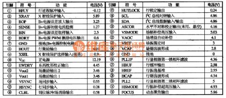
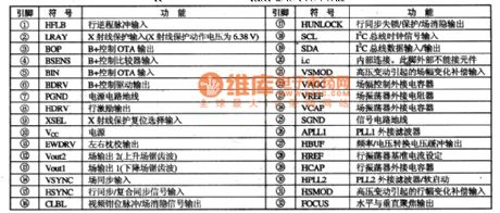
The line oscillator and field oscillator's line oscillation frequency and field oscillation frequency of the TDA4857 can be changed by the line & field sync signal. The line oscillator's free oscillation frequency is 31.45kHz, the line frequency operating range is 50 to 130kHz, the field frequency operating range is 50 to 60Hz. This circuit's field excitation signal output is the differential output mode, that means this circuit outputs the rise field sawtooth wave and the down field sawtooth wave to drive the DC-coupled field output circuit. This circuit also has the soft-start function, the X-ray protection function and the +B switching power supply control circuit, the integrated block internal box circuit is as shown in figure 13.
2.Pin functions and data
The pin functions and data of the TDA4857 is shown as the table 19, the waveform of the critical pin is as shown in figure 13.
Table 19 The pin functions and data of the TDA4857
(View)
View full Circuit Diagram | Comments | Reading(1865)
MN67730MH digital DVD audio decoding integrated circuit
Published:2011/5/5 21:49:00 Author:Sharon | Keyword: MN67730MH, digital DVD, audio decoding, integrated


MN67730MH IC pin functions and data
MN67730 IC critical pin wave
MN67730MH is a digital DVD audio decoding integrated circuit produced by Panasonic andwidely used in DVD player movement of Panasonic movement series .
1. Features:MN67730MH integrated circuit includes MPEG-1 decoding circuit, MPEG-2 decoding circuit, AC-3 decoding circuit, linear PCM decoding circuit, constant voltage circuit, clock oscillation circuit, microprocessor interface data bus circuits and other ancillary circuitry.2. IC pin functions and data: MN67730MH integrated circuit is sealed in Quartet 80-pin package. The pin functions and data is listed in the Table, and the critical pin waveform is shown in the figure. (View)
View full Circuit Diagram | Comments | Reading(965)
| Pages:1949/2234 At 2019411942194319441945194619471948194919501951195219531954195519561957195819591960Under 20 |
Circuit Categories
power supply circuit
Amplifier Circuit
Basic Circuit
LED and Light Circuit
Sensor Circuit
Signal Processing
Electrical Equipment Circuit
Control Circuit
Remote Control Circuit
A/D-D/A Converter Circuit
Audio Circuit
Measuring and Test Circuit
Communication Circuit
Computer-Related Circuit
555 Circuit
Automotive Circuit
Repairing Circuit