
Circuit Diagram
Index 1943
Guangzhou Honda remote control starting/safety warning system circuit diagram
Published:2011/5/6 0:45:00 Author:muriel | Keyword: Guangzhou Honda , remote control starting/safety warning system
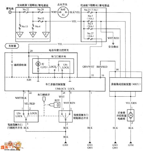
Guangzhou Honda remote control starting/safety warning system circuit diagram is as shown
(View)
View full Circuit Diagram | Comments | Reading(632)
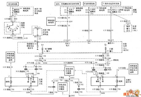
Guangzhou Honda Accord 2.4L ambient Light, roof lamp circuit diagram
Published:2011/5/6 0:49:00 Author:muriel | Keyword: Guangzhou Honda Accord, 2.4L , ambient Light, roof lamp

Guangzhou Honda Accord 2.4L ambient Light, roof lamp circuit diagram is as shown
(View)
View full Circuit Diagram | Comments | Reading(1125)
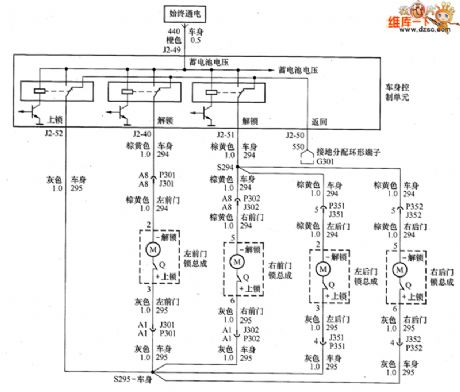
Buick GL8 commercial vehicle central door lock system circuit diagram
Published:2011/5/6 0:51:00 Author:muriel | Keyword: Buick GL8 commercial vehicle , central door lock system
Buick GL8 commercial vehicle central door lock system circuit diagram
(View)
View full Circuit Diagram | Comments | Reading(1525)
Buick LaCROSSE 2.4L motor-driven car window circuit diagram
Published:2011/5/6 0:53:00 Author:muriel | Keyword: Buick LaCROSSE , 2.4L , motor-driven car window
Buick LaCROSSE 2.4L motor-driven car window circuit diagram is as shown
(View)
View full Circuit Diagram | Comments | Reading(503)
Buick starting control system circuit diagram
Published:2011/5/6 1:02:00 Author:muriel | Keyword: Buick, starting control system
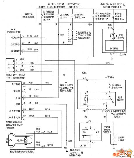
Buick starting control system circuit diagram is as shown
(View)
View full Circuit Diagram | Comments | Reading(484)
Time Base Trigger Circuit
Published:2011/5/6 1:11:00 Author:Sue | Keyword: Time Base, Trigger

View full Circuit Diagram | Comments | Reading(755)
6n11 electron tube power amplifier production of information circuit diagram
Published:2011/4/12 9:11:00 Author:Nicole | Keyword: electron tube

The circuit structure of tube preamp have many forms, this preamp adopts improved SRPP circuit + cathode output circuit, shown in Figure 1. Because the SRPP circuit has the features of minimal distortion, wide frequency response and low noise.
The circuit with low output resistance is very popular, the SNR of improved SRPP circuit can improve about 20dB than before, the highest SNR of general SRPP circuit is only 60dB, and the improved SRPP circuit can reach 80dB. Its form voltage gain and resistance capacity coupled amplifier are about the same, dynamic is also nearly the same, electric efficiency is not high, but it is suit for CD and some large dynamic range signal sources, it can be used as input stage, because the efficiency of SRPP circuit is not high, so it adds a first level cathode loaded amplifier, the cathode loaded amplifier has characteristics of low output resistance, bandwidth, low distortion, and it is easy to push any backward stage amplifier.
(View)
View full Circuit Diagram | Comments | Reading(4423)
Piezoresistive integrated pressure sensor circuit
Published:2011/5/5 22:53:00 Author:Sharon | Keyword: Piezoresistive, integrated, pressure sensor

To deal with temperature drift of sensor's sensitivity, the general method of compensation is to change the supply voltage. With the development of semiconductor technology, there has emerged integrated piezoresistive pressure sensor, which is monolithic integrated pressure sensor composed of electric bridge formed by four sense resistors, the voltage amplifier, and the temperature compensation circuitry. The Graph is its circuit diagram and scheme. Owning to the temperature compensation circuit and differential amplifier that integrated pressure sensor applied, its sensitivity temperature coefficient is almost amount to zero. (View)
View full Circuit Diagram | Comments | Reading(1681)
6sn7 electron tube preamp line circuit diagram
Published:2011/4/17 7:29:00 Author:Nicole | Keyword: electron tube, preamp line

Used 6SN7 as preamp amplification circuit with negative feedback, the figure is as below. It uses 6S8P electron tube of the dawn in this circuit, high voltage power supply adopts 6Z4 as rectifier, and uses two inflatable tubes as voltage regulator, the filament is AC powered, but the filament ground adopts arms resistance balance method to reduce the communication noise.
This circuit is very easy to make, the characteristics of sound is its first class thick and smooth of mediant, but the power is normal and the sound field is weak, it’s unkown whether the intermediate frequency’s performance is too excellent to overshadowed the high and low frequency, its frequency domain extension, dynamics and transient state are not very overstanding, the timbre seems like classic LS3/5A. From the side of Hi-fi, its sound effect is not complete, but it is also pleasurable, especially when we are playing the violin stringed music and person's voice, it is quite satisfying. If this circuit uses the electron tube of the Former Soviet Union’ 6H8C or the US GE’ 6SN7, its power and sound field' analysis can be improved, but the 6SN7 which was made by GE in the 70s is not better than 6H8C in the sound’s smooth, unless we can find the products which are produced in the 60s. Compared to the 6N11 first level cathamplifier and the next SRPP 6N10 preceding stage, its individuality is higher, the medium frequency band is excellent for people auditory impression.
(View)
View full Circuit Diagram | Comments | Reading(12342)
Digital Servo Integrated Circuit
Published:2011/5/6 1:12:00 Author:Sharon | Keyword: Digital Servo, Integrated


MN67700 IC pin arrangement and related waveforms
MN67700 IC pin functions and data
MV67700 is Panasonic's new DVD digital servo IC, widely used in Panasonic series, Malata, TCL, Konka DVD players.
1. Functions and features: MV67700 integrated circuit includes servo DSP circuit, multiple analog / digital converter circuit or digit/ analog conversion circuit, pulse width modulation circuit, computer interface and multi-purpose interface circuit and the expected error control circuit. It's used for focusing, tracking, and the spindle error signal changing into a digitized operations so as to output servo control signals for servo control of the relevant circuit.2. Pin functions and data: MN67700 IC package applied four flat structure, the pin arrangement shown in Figure (e), and date listed in the table. Letters in Waveform column in the table represent waveforms shown in Figure 8 (a) - (d).
(View)
View full Circuit Diagram | Comments | Reading(759)
Temperature Drift Compensation Circuit
Published:2011/5/6 1:33:00 Author:Sharon | Keyword: Temperature drift, Compensation

In order to solve the problem of temperature drift, for power supply on the electric bridge, it usually applies constant current source power supply.However, due to the production process and other reasons, the resistance of the bridge are not equal, and there is zero-bit output.So, even the constant current source power supply is applied, there still will be a certain temperature error.
Piezoresistive pressure sensor not only has the phenomenon of zero-bit temperature drift, but also its sensitivity changes with temperature.Piezoresistive pressure sensor's zero drift can be solved by series and parallel of the thermistor in bridge circuit, as shown in the picture.RT is thermistor which is mainly used to compensate for zero drift; RP is used to adjust the zero output. (View)
View full Circuit Diagram | Comments | Reading(1253)
The Amplifier Circuit of Low Capacitance with High Resistance
Published:2011/5/6 1:47:00 Author:Startrek | Keyword: Amplifier Circuit, Low Capacitance, High Resistance

This multiple series feedback circuit can provide high-input impedance and stable wideband gain for general video amplifiers. (View)
View full Circuit Diagram | Comments | Reading(564)
Impedance Bridge Amplifier Circuit
Published:2011/5/6 1:47:00 Author:Startrek | Keyword: Impedance Bridge, Amplifier Circuit

Impedance Bridge Amplifier Circuit (View)
View full Circuit Diagram | Comments | Reading(1116)
The Inside Circuit of the Power Operational Amplifier
Published:2011/5/6 1:47:00 Author:Startrek | Keyword: Inside Circuit, Power Operational Amplifier

This circuit can provide a voltage of 90KHz and 180V for 4M, and PA04 can even provide a power of 400W with low THD for 8C when the frequency is over 20KHxz.
(View)
View full Circuit Diagram | Comments | Reading(511)
Triangular-Wave Carrier Generator Circuit
Published:2011/5/6 1:46:00 Author:Startrek | Keyword: Circuit Generator, Triangular-wave

As in the following figure, the triangular-wave diagram consists of two OPs, and the mark of R62 represents the adjustment of OFFSET, while R27 represents the adjustment of peak value. With the help of the switch, we canlink todifferent resistences, then triangular-waves with different frequencies can be made out.
(View)
View full Circuit Diagram | Comments | Reading(930)
The Instrumentation Amplifier Circuit with Common Mode Signal Input
Published:2011/5/6 1:46:00 Author:Startrek | Keyword: Instrumentation Amplifier, Common Mode

The Diagram of Instrumentation Amplifier with Common Mode Signal Input (View)
View full Circuit Diagram | Comments | Reading(3767)
6N10 SRPP preamplifier circuit diagram
Published:2011/4/8 2:42:00 Author:Nicole | Keyword: preamplifier, SRPP

The third preamp uses 6N10 as SRPP circuit, As shown in the figure, this circuit is wide spread, at present, I believe many readers have welded, SRPP is called Shunt Regulator Push-Pull, this circuit has the advantages of excellent linearity, low distortion, high magnification, high dynamic and low output impedance and so on, The performance are better than ordinary typical circuit of common cathode interconnect RC or the last stage as cathode follower, it is in accordance with the conditions of an ideal preamp.
The principle of SRPP is a transistor as the common cathode grounded to enlarge in the below, the gain depends on the anode impedance, most are happened on the top of the transistor, while the upper transistor is a current source, as the changes active load of the following transistor. In addition, the above transistor also can be used as a cathode follower coupler, the signal is outputed to the above transistor grid by the below transistor screen.
(View)
View full Circuit Diagram | Comments | Reading(3949)
The non-Inverting D.C Amplifier Circuit with NPN and PNP
Published:2011/5/6 1:46:00 Author:Startrek | Keyword: non-Inverting, Amplifier Circuit

The non-Inverting Amplifier Circuit with NPN and PNP (View)
View full Circuit Diagram | Comments | Reading(2078)
Electric Bicycle Storage Battery Charger(UC3842) Circuit
Published:2011/5/6 0:52:00 Author:Sue | Keyword: Electric Bicycle, Storage Battery, Charger
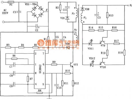
View full Circuit Diagram | Comments | Reading(3183)
MC3406A buck-boost DC-DC convertor integrated circuit diagram
Published:2011/5/5 7:32:00 Author:Nicole | Keyword: Integrated convertor


MC3406A is a new monolithic buck-boost DC-DC converter integrated circuit, the input voltage is 3 ~ 40V, output voltage isadjustable, the output switch current can up to l. 5A, and it hasa temperature compensated voltage reference, it has the function of current limit. The IC is equipped with only a few external components, then it can form boost, buck, anti-transition DC-DC converter, it can be widely used in various portable instruments, meters and so on.
MC3406A used as boost DC-DC convertor circuit:
MC3406A used as buck DC-DC convertor circuit:
MC3406A used as anti-transition DC-DC convertor circuit:
(View)
View full Circuit Diagram | Comments | Reading(3629)
| Pages:1943/2234 At 2019411942194319441945194619471948194919501951195219531954195519561957195819591960Under 20 |
Circuit Categories
power supply circuit
Amplifier Circuit
Basic Circuit
LED and Light Circuit
Sensor Circuit
Signal Processing
Electrical Equipment Circuit
Control Circuit
Remote Control Circuit
A/D-D/A Converter Circuit
Audio Circuit
Measuring and Test Circuit
Communication Circuit
Computer-Related Circuit
555 Circuit
Automotive Circuit
Repairing Circuit