
Circuit Diagram
Index 1944
Mains supply overvoltage protection circuit with good performance
Published:2011/4/18 9:56:00 Author:Nicole | Keyword: mains supply, overvoltage protection


In electric power lacking areas, the power supply is very unstable, the peak value is only about 170V, at night, it is over 250V, in order to protect the expanding household appliances, it is needed to deploy a overvoltage protector.
The circuit is as shown, it adopts capacity depressurization and simple regulated power supply circuit, when the power supply is normal, the TL431C control pole voltage is lower than 2.5V, TL431C circuit is not conductive, realy contact is open. When the mains power reached 250V, after rectifier filter, the current is 3.3mA, the voltage drop on R3, diode and regulator tube(including LED) is 11V and 26V. 37V voltage is divided by R1, R2, then A point voltage is 2.55V, TL431C circuit turns on, relay K pull-in, mains power is a short circuit, then the power supply over current device is tripping or fuse burn-out, it can protect household appliances. To series connect a small resistance in contact loop, it can protect contact from burning off due to the overlarge short-circuit current. Because the capacitance of capacitor C3 is larger, it can store large charge to add on the relay coil, then the relay contact will keep 0.2s pull-in time, it is enough to make over current device trip or fuse burn-out.
(View)
View full Circuit Diagram | Comments | Reading(2149)
Broadband Square Wave Signal Generator Circuit Composed of CD4046
Published:2011/5/6 0:02:00 Author:Sue | Keyword: Broadband, Square Wave, Generator
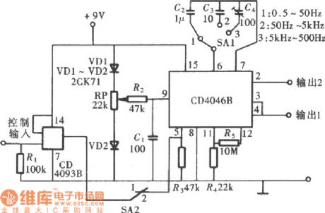
The working frequency of CD4046 can reach 1Mhz at most. By setting the parameter of its outside component RC, we can get a broadband square wave signal generator. The circuit is shown in the figure below. (View)
View full Circuit Diagram | Comments | Reading(2889)
Switch Power Charger Circuit
Published:2011/5/6 0:52:00 Author:Sue | Keyword: Switch Power, Charger

View full Circuit Diagram | Comments | Reading(668)
Radiation thermometer electricity testing temperature between 100-500℃
Published:2011/4/27 9:14:00 Author:Nicole | Keyword: Radiation thermometer, test temperature
This radiation thermometer uses lead sulfide photosensitive resistance 61SV as infrared radiation detector. In order to avoid the surrounding radiation mixing in measured value, so the measured radiationshould bemodulated by 350Hz frequency. Adopting filter which is composed of Ge or silicon to isolate the visible radiation.
When the voltage of photosensitive resistance is constant, and the temperature is in the range of 100~500℃, the singal value is changed about 1000 times. The total testing range is divided into 5 grades, using transfer switch S1 and S1' to choose.
The whole amplifier circuit is divided into 4 classes. Connecting a bridge rectifier circuit to last stage negative feedback amplifier to change the AC singal into DC singal. The measured value is displayed by moving coil meter(the measuring range is 200μA). (View)
View full Circuit Diagram | Comments | Reading(440)
80Vp - p Output Suspended Load Amplifier Circuit
Published:2011/5/5 2:58:00 Author:Joyce | Keyword: 80Vp - p Output, Suspended, Load, Amplifier, FX3140, FX3140B
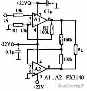
80Vp - p output suspended load amplifier circuit is shown in the graph below.This circuit uses a high input impedance op-amp FX3140B.In dual power supply of 22V,the output will reach its peak ,which is more than 40V.The slew rate is 9V/s, the input bias current is10pA, the offset current is 0.5 pA, and the offset voltage is1mV.The load is connected between the output of the two op-amps ,whose output voltage Uo is 2U1, and the maximum output voltageis 80Vp - p. The decoupling of power supply uses 0.1 u F ceramic capacitors connecting foot 7, 4 of FX3140 with the ground in the shortest distance. A metal film resistor with the precision of 1% is used as the resistance .
(View)
View full Circuit Diagram | Comments | Reading(572)
Digital long delay circuit
Published:2011/4/20 9:10:00 Author:Nicole | Keyword: digital, long delay


Ordinary long time delay circuit is usually with the help of electrolytic capacitor or high impedance circuit. This circuit has poor stability, and the accuracy of delay also is not high.
Here is a digital long delay circuit, it casts behind the electrolytic capacitor and high impedance circuit absolutely, the accuracy of delay is high.
The core of this circuit is the integrated block MC14521B, it is a 24 class clock division circuit, it contains inverters which composed of oscillation circuit. If the trigger input terminal is grounding or without signal, then the circuit is into delay state, the delay time is adjusted by the range switch X and 100KΩ potentiometer.
If X is connected to point A, the delay time is from 1 minute 40 seconds to 18 minutes 30 seconds, if X is connected to point B, the delay time is from 13 minutes 20 seconds to 2 hours 28 minutes. If X is connected to point C, the delay time is from a hour 47 minutes to 20 hours. The specific delay time is set by 100KΩ potentiometer. If it needs longer delay, you can use bulky capacitor insteads of 39nF capacitor. Then the delay time will reach more than one week. Added a positive signal on the trigger input terminal, the divider in 4521B can be reset.
The delay is reliable and steady, it can use 6~15V regulated power supply. The prototype adopts 12V power supply.
(View)
View full Circuit Diagram | Comments | Reading(742)
Eight-way electric heater sequence delay switch control produced by 89C2051
Published:2011/4/22 19:17:00 Author:Nicole | Keyword: electric heater, switch control

After energizing, 89C2051 resets, and P1.0 ~ P1.7 all the indicator lights off. P3.0 and P3.1are set to high level, to test whether there is start-up singal input in P3.0 port. When S1 is pressed, the start-up singal inputs P3.0 port, after avoiding flutter deal and confirmed by the program, the P1.0 port is set to low level immediately, LED8 lights, OPT08, Q8, J8 turn on, J8 normally open contact is closed, to turn on and control the AC contactor power supply of the first load electric water heater, the first load electric water heater starts working; after 10 seconds delay, the P1.1 port is set to low level, LED7 lights, OPT07, Q7, J7 turn on, J7 normally open contact is closed, to turn on and control the AC contactor power supply of the second load electric water heater, the second load electric water heater starts working; sothe power supply of the eighth load electric water heater is openedat last, thus, the electric water heaters from the first load to the eighth load are all in working condition. (View)
View full Circuit Diagram | Comments | Reading(1191)
Resistance-capacitance trigger unidirectional SCR dimming light circuit
Published:2011/5/5 7:33:00 Author:Nicole | Keyword: resistance-capacitance, unidirectional SCR, dimming light

The circuit is as shown, it is a trigger unidirectional SCR dimming light circuit which is composed of resistance-capacitance components, 220V AC power supply is changed into DC pulse voltage by VD1~VD4 bridge rectifier, it is added to the anode and cathode of SCR VT. The trigger circuit consists of RP、R and C2, DC pulse voltage charges to capacitance C2 by RP、R, when it is charged to a value, SCR VT turns on, bulb E turns on and shines. When the pulse is added to the anode and cathode of VT is zero passage, VT automatically turns off, the power supply charges to C2 by RP、R, the circuit will repeat above operations. To adjust potentiometer RP, then it can change the charge rate of C2, so it can change the conduction angle of SCR VT, then the current effective value which flows bulb E will change, it can achieve stepless dimming's purpose. The feature of this circuit is low cost, the shortage of it: the voltage between the two poles of bulb will change in relation to temperature and input pressure. (View)
View full Circuit Diagram | Comments | Reading(1278)
Automatic delay light switch circuit
Published:2011/4/26 3:54:00 Author:Nicole | Keyword: light switch

The working principle: the circuir is as shown. A, B are connected to the two terminals of switch. Closing switch S, the positive half cycle of AC will trigger SCR turn-on by D6、R2、R1、D1 and SCR control pole; the negative half cycle of AC by D4、R2、R1、D1 and SCR control pole will trigger SCR turn-on. After SCR turn-on, it is equal to short circuit C, D points, so A, B pointsare closed by diode and the turn-on SCR. The light is on.
After switch S off, the SCR still has trigger current and keep conductive, due to the capacitor C1 is discharging to it by R1, D1 and SCR control pole. The current is decreasing, after a few minutes, SCR off, then light goes out. The delay time is about 40~50s.
The component selection: to choose SCR with 1A maximum current, 400V voltage. 1N4004 can be used for D1、D3~D6. C1 adopts 630V, 35μF color capacitor. After closing switch S, the light is not on, you can decrease the resistance of R1 properly. (View)
View full Circuit Diagram | Comments | Reading(939)
Novel touch switch table lamp circuit
Published:2011/5/5 7:35:00 Author:Nicole | Keyword: touch switch, table lamp

The circuit is as shown, it is divided into four grades to control the brightness of lamp. After connected to power supply, the light is not on, then you cantouch the lampshade metal shell for the first time. The bulb will emit low bright light. To touch it for the second time, the bulb will emit middle bright light, to touch it for the third time, the bulb will emit brightest light, to touch it for the fourth time, the bulb will off, as it order cycle. The prone failure of this circuit is TRIAC 97A6 breaks down and the poor contact between lampshade metal shell and circuit touch input terminal.
When I am debugging this circuit, using GS6061 to replace TT6061 and 1N4007 replace 1N4004, the other components are the same. It is proved that the circuit works well, it can achieve the functions as above. But TRIAC is easy to damage, so you can parallel a protection circuit which is composed of a series of resistence and capacitance on the two terminals of SCR. (View)
View full Circuit Diagram | Comments | Reading(1793)
Color lamp control circuit composed of SH808 multifunction music color lamp program control integrated circuit
Published:2011/5/5 7:36:00 Author:Nicole | Keyword: color lamp, program control

SH808 has music memory function, it can produce 16 songs and drive color lamp series, it will flash with music rhythm. Besides, the color lamp series will present racing horse jumping, chasing each other flashing, rolling waves and some flashing effects. These functions are divided into 8 program states: ①light series areall lighting without music. ②light series are flashing with music(repeat from 1~16 songs). ③light series are flashing with music(repeat from 1~4 songs). ④light series are flashing with music(repeat from 5~8 songs). ⑤light series are flashing with music(repeat from 9~12 songs).⑥light series are flashing with music(repeat from 3~16 songs). ⑦light series present racing horse jumping, chasing each other flashing, without music. ⑧light series present rolling waves, without music. (View)
View full Circuit Diagram | Comments | Reading(773)
Timed street light circuit with light control
Published:2011/5/5 7:49:00 Author:Nicole | Keyword: timed street light, light control
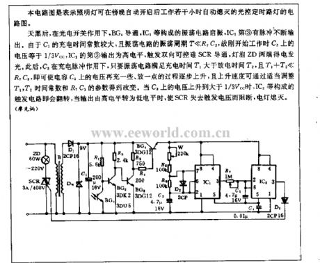
It is an optical control timing street lamp circuit diagram, at night-fall the floodlight will automatically turn on, after a few hours later, it can automatically turn off.
After dark, by the action of photoelectric switch, BG4 turns on, the oscillation circuit composed of IC1 starts to oscillate, ③ pulse constantly output. Because the charge time constant is larger, and the oscillation period T< (View)
View full Circuit Diagram | Comments | Reading(1197)
WT8089 16 kinds of colored lamp patterns with eight pieces of music automatically control circuit
Published:2011/5/5 7:46:00 Author:Nicole | Keyword: color lamp pattern, music


The circuit is as shown. This circuit is composed as the core of WT8089, when it is playing a pretty electronic music, it can produce 16 kinds of different parrents dance methods. MODE terminal is actumatically controlled by clock pulse generator and the rhythm pulse is sent by shaping circuit, it can make the four kinds of color lamp control methods achieve automatical cycle and jumping. A low frequency pulse generator is composed of four 2 input terminal and the gate F1, F2 of negation gates IC CD4011 and resistor capacitor component, gates F3, F4 are connected to a RS trigger, it can trowel the waveform sent by oscillator, then it will change into standard square wave singal, it is added to MODE terminal (seven foot) of IC2, it can achieve automatical cxontrol for color lamp control method. The oscillation period of RC oscillator is
The oscillation period is adjusted in the range of 4~16s. To adjust RP1, it can coordinate color lamp's 16 kinds of changes and the rhythm of electronic music, good flashing jumping and feeling of music, the audio-visual effect is nice. (View)
View full Circuit Diagram | Comments | Reading(516)
Touch delay light circuit with time base circuit(1)
Published:2011/5/5 7:49:00 Author:Nicole | Keyword: Touch delay light, time base

The figure is as shown, it adopts NE555 as core component to form the touch delay light circuit, the featureare precise delay time, good circuit repeatability. When you touch it one time, the light Ewill keeplighting about 150s. (View)
View full Circuit Diagram | Comments | Reading(1735)
Delay light circuit with time base circuit(1)
Published:2011/5/5 7:44:00 Author:Nicole | Keyword: Delay light, time base

The figure is as shown, the NE555 is made as the core component to consist this delay light circuit. VD2, VS, C3, C4 form a simple diode rectifier steady voltage circuit, after connecting to power supply, the two terminals of C3 will output about 12V DC volgate to provide the whole circuit. NE555 time base circuit is connected into monostable working mode, C1 is full up charge, so NE555 threshold value or ⑥ foot is high level, time base circuit is in reset state, the ③ foot is low level, relay K has no action, light E offs. At this time, LED is lighting, it is used to indicate the switch position, it is convenient to find switch at night. (View)
View full Circuit Diagram | Comments | Reading(498)
Delay light circuit with time base circuit(2)
Published:2011/5/5 7:40:00 Author:Nicole | Keyword: Delay light, time base

The figure is as shown, after turning off the light, the circuithas no power consumption. Relay K should use small electromagnetic relay with two groups of transfer contacts, such as JRX-13F、DC12V and so on. (View)
View full Circuit Diagram | Comments | Reading(403)
The circuit diagram of SH-804 festival multi-pattern color lamp with voice control function
Published:2011/5/5 7:39:00 Author:Nicole | Keyword: multi-pattern color lamp, voice control


The circuit is as shown. It consists of clock beat generator, light control circuit, laughing phonation circuit and AC depressurization rectifier circuit. SH-804 is a CMOS color lamp program control special integrated circuit, it has ten kinds of circulation transform ways and six kinds of dimming light change speed such as up slowly fading, horse racing, jumping, smooth water, pour water, waves rolling, starsflashing and all brightness. The transform ways can automatically cycle changing, it also can artificial set flashing patterns through key terminal. This circuit adopts clock pulse automatic key way , to achieve the flashing patterns' automatic changing. F1~F4 is four 2 input terminal Nand, CMOS is IC CD4011, the F1, F2 and R2, C1 form a low frequency clock generator, the clock frequency is:
(View)
View full Circuit Diagram | Comments | Reading(559)
Using calculator as count circuit
Published:2011/5/5 7:53:00 Author:Nicole | Keyword: calculator, count

This circuit uses MM7536calculator chip, two DM75491 segment drivers and a DM75492 bit driver. Those three drivers are used to drive NSN66A LED 6bits display. This counter is manual controlled by three switch. In order to restoration, it can use S1 to make calculator reset. S2 can input 1, if it needs to press new number, you can connect to S3, Vcc provides current to LED through limiting resistance, because Vcc's voltageis lower than Vss, so this method can save power consumption. This circuit can drive lager LED display. (View)
View full Circuit Diagram | Comments | Reading(753)
Photoelectric switch circuit in AC network
Published:2011/5/5 7:53:00 Author:Nicole | Keyword: photoelectric switch, AC network
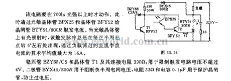
When the light intensity is more than 700lx, this circuit will take action. The light-sensitive transistor BPX25 and transistor BFY52 provide SCR BTY91/800R with trigger current. When the light-sensitive transistor has light, this trigger pulse always appears about 6°behind each positive half cycle starting point, the maximum arithmetic mean value of DC half wave current flows load is 16A.
The regulator tube BZY88/C5 and transistor T1, the connected resistance 390Ω are used to limit trigger circuit voltagenomore than 6V. Diode BYX45/800R is used to break negative half cycle network voltage, the resistance 33Ω and capacitance 0.1μF are used to protect SCR, it can prevent overvoltage. (View)
View full Circuit Diagram | Comments | Reading(621)
Light Control Street Lamp Circuit Using ne555
Published:2011/5/5 20:25:00 Author:Robert | Keyword: Light Control, Street Lamp

As shown this circuit is specially designed. The light control switch and the electrical networks are connected by the two-wire connected method. It can replace the general switch directly to make the normal lamps be the light control automatic street lamps.
(View)
View full Circuit Diagram | Comments | Reading(2968)
| Pages:1944/2234 At 2019411942194319441945194619471948194919501951195219531954195519561957195819591960Under 20 |
Circuit Categories
power supply circuit
Amplifier Circuit
Basic Circuit
LED and Light Circuit
Sensor Circuit
Signal Processing
Electrical Equipment Circuit
Control Circuit
Remote Control Circuit
A/D-D/A Converter Circuit
Audio Circuit
Measuring and Test Circuit
Communication Circuit
Computer-Related Circuit
555 Circuit
Automotive Circuit
Repairing Circuit