
Circuit Diagram
Index 1942
Homemade photo-couplers Circuit
Published:2011/5/5 2:06:00 Author:chopper | Keyword: photo-couplers

Combine the Φ55mm, red LED with photoresistance by transparent tape and put them in a pigmented penholder(black for good),and then seal both end,which has made a photo-coupler.Photo-coupler can applies to low frequency switch circuits ,just as shown in picture a.And picture b shows an outage alarm circuit adopting photo-couplers that can make an alarm if the electricity is not available.As usual,the red LED is ashine and the photo-coupler reduce the resistance of photoresistance through coupling.So,VT1 stops working,and the oscillator comprised by VT1、VT2 stops as well.When meet a commercial power cut, the resistance increases and makes VT1 connected,so that the oscillator starts to run,giving out a warning signal. (View)
View full Circuit Diagram | Comments | Reading(991)
The Circuit of Simple Front-end Amplifier with Adjustable Gain
Published:2011/5/6 3:17:00 Author:Startrek | Keyword: Front Amplifier Circuit, Simple Power Adjustment

Inthis circuit, 1/4 of itcomposes a front-end amplifier with a simple power adjustment,while R7 controls the power, and if again of 10 times or more is needed, the front-end amplifier with a device parameter in the following figure can be in use.
(View)
View full Circuit Diagram | Comments | Reading(617)
Amoi DVD Power(UC3842) Circuit
Published:2011/5/6 2:06:00 Author:Sue | Keyword: Amoi, DVD, Power
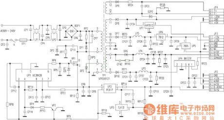
View full Circuit Diagram | Comments | Reading(3474)
No polar electrolysis capacitor aging circuit diagram
Published:2011/5/5 3:31:00 Author:Crystal Liu | Keyword: no polar electrolysis capacitor, aging circuit

No polar electrolysis capacitor refined circuit. (View)
View full Circuit Diagram | Comments | Reading(566)
Three voltage regulator series connection acquired 0-284V voltage circuit diagram
Published:2011/5/5 4:35:00 Author:Crystal Liu | Keyword: three voltage regulator series connection , acquired 0-284V voltage circuit diagram

Three voltage regulator series connection acquired 0-284V voltage circuit diagram (View)
View full Circuit Diagram | Comments | Reading(428)
The figure of TA7766F low voltage stereo coding integrated circuit
Published:2011/4/22 1:56:00 Author:Crystal Liu | Keyword: low voltage, stereo, coding integrated circuit


TA7766F low voltage stereocoding integrated circuit is produced by TOSHIBA.1.The internal circuit figure and the pin functions of TA7766F.The integrated package of TA7766F contains amplifying circuit,stereo\single track switch;The circuit of stereo Decoding ,Voltage controlled oscillator circuit,frequency dividing circuit,direct current amplifier and stereo indicator light controller.The integrated blocks within circuit is shown in figure 1.This lC adopt double row flat 16 feet, the integrated circuit encapsulation structure of pin function and data listed see table 1.
2.TA7766F main electric parameters.TA7766F work power voltage range of integrated circuit for 0.9-2V,typical working voltage is 1.5 V.Its ultimate conditions of use in Ta = 25 ℃, the power supply voltage, allow the Vcc = 2V PD = 35OmW, indicator power drive current I (LAMP)5mA .
3.TA7766F typical application circuit.
The typical application of manifold blocks TA7766F circuit shown in figure 2.4.Circuit working process.
From TA7766F (2) composite signal input, demodulation of feet after about from (15) channels signal, (16) feet, output, send the latter stage circuit. ⑩ feet external stereo instructions light-emitting diodes that the light emitting diode feet wide by 9 sensitivity resistance can be adjusted. The voltage controlled oscillation in circuit Vco) circuit (by 6 feet external LC resonant circuit can fine-tune Vco frequency.5. Breakdown maintenance tips
When couldn't receive FM stereo programs, and can only receive FM mono programs, stereo indicator light point not bright, but check TA7766F (11) feet wide capacitance, because without short-circuit failure feet (11) if because of capacitance, the yi short-circuit grounding. Stop vibration, stereo decoding circuit doesn't work. Then check (13) feet ChanSheng/stereo conversion switch, if switch can't switch to stereo position, (13) foot has high potentials and Vco also stop vibration without stereo. Step 3 check 6 feet of LC network, when capacitance normal, the radio to the stereo position, re-adjusted L, observe whether indicator lights. Stereo sound If it is not bright and check without problems, then, luminous tube TA7766F measured again all the pins voltage and listed in table 1, comparing the normal whether judge this lC failure. Such as voltage, and check deviation is a deviation feet peripheral components are TA7766F communicqtion problem, then explaining damage.
(View)
View full Circuit Diagram | Comments | Reading(903)
TA8859CP image geometric distortion correction circuit
Published:2011/5/6 2:39:00 Author:TaoXi | Keyword: image, geometric distortion, correction
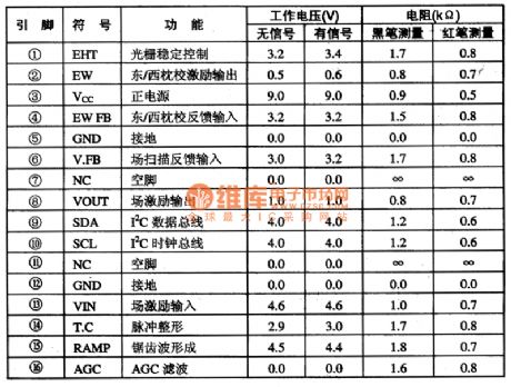
The TA8859CP is designed as one kind of image geometric distortion correction circuit that is produced by the TOSHIBA company, and it can be used in the large screen and rear projection TV's scanning part.
1.Features
The TA8859CP has the vertical linear compensation and S correction circuit, the parabolic wave circuit, the field scanning sawtooth wave circuit, the trapezoidal distortion correction circuit, the line/field linear adjustment circuit, the line/field center adjustment circuit.etc.
2.Pin functions and data
The TA8859CP can be used in the Konka BT5O01-type rear projection TV, the pin functions and data is as shown in table 1.
Table 1 The pin functions and data of the TA8859CP (View)
View full Circuit Diagram | Comments | Reading(612)
Schematic of The Encoded Three-Channel Transmitter and Receiver Composed Of KIA733P and KIA7657P
Published:2011/4/26 9:06:00 Author:TaoXi | Keyword: Encoded, Three-Channel, Transmitter and Receiver
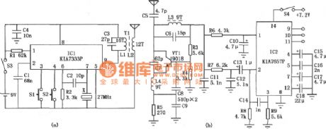

By encoding the transmitter circuit, the 3 channels of the receiving circuit can be used in different applications, remote control three kinds of circuits. The coded transmission circuit is shown in Figure (a).
The receiving circuit is shown in Figure (b). IC2 is the receiver decoder IC (KIA7657P) which includes two-stage amplifier, automatic adjustment circuit, decoder and three pairs of compound (darlington) driver tube, additionally, it has a 5V power supplier to supply power to the whole circuit. The C14、R8、R9 between 2 pin and 3 pin are amplification gain and automatically adjustment components, Cl5~Cl8 are the amplifier capacitor decoder and filter capacitor decoder. The 9~11 pins of the IC2 export the decoding signal, available in low level, and the sink current can be up to 100mA. This circuit issuitable to control the toy, electric curtain, automatic door, crane and construction crane.
Figure 1. Schematic of The Encoded Three-Channel Transmitter and Receiver Composed Of KIA733P and KIA7657P
Shown in Table 1. (View)
View full Circuit Diagram | Comments | Reading(710)
audiphone circuit made of discrete components
Published:2011/5/4 9:33:00 Author:TaoXi | Keyword: audiphone, discrete components

1. Principle
The audiphone circuit made of discrete components is as shown in figure 1, it is the multi-stage audio amplifier which is composed of a transistor VT1 ~ VT3. The typical RC coupled amplifier is composed of the VT1 and external RC components, this amplifier is the front audio voltage amplifier; the two-stage direct coupling type power amplifier circuit is composed of the VT2 and VT3, VT3's output impedance is low to work with the 8Ω low-impedance headphone.
2. Component selection
VT1 and VT2 select the 9014 or 3DG8 silicon NPN low power, low-noise transistor, and the current amplification coefficient is β≥100; VT3 selects the 3AX31 Ge PNP low power transistor, the current Iceo is β≥30.
B selects the CM-18W (φ10mm×6.5mm) high sensitivity electret microphone, and it has five levels of sensitivity which are indicated by the color dots: red is -66dB, light yellow is -62dB, dark yellow is -58dB, blue is -54dB, white is >-52dB. This device need to use the white dot to have high sensitivity. B can also use the electret microphone with blue dot and high sensitivity.
(View)
View full Circuit Diagram | Comments | Reading(1175)
The dual component sine table wiring circuit diagram of three-phase reative energy meter with 60-degree of phase angle differential
Published:2011/5/6 2:41:00 Author:TaoXi | Keyword: dual component, sine table, three-phase, reative energy meter, 60-degree, phase angle differential

The The dual component sine table wiring circuit diagram of three-phase reative energy meter with 60-degree of phase angle differential is as shown:
(View)
View full Circuit Diagram | Comments | Reading(2666)
SCR Dimmer Circuit used for 230V Incandescent lamps
Published:2011/4/28 18:44:00 Author:Christina | Keyword: 230V Incandescent, SCR Dimmer

1.The basic model traic dimmer
2.The practical model traic dimmer
3.The minimum brightness adjustable traic dimmer
In most cases, we hope the minimum brightness of the bulb will be stable after sw1 close-up, so access r2 in this circuit can achieve this purpose. If we change r2 to the variable resistor, the adjustment will be more accurate.
4.Withthe light-steady function dimmer
When the ambient light changes, resistance value of cds will be change too, this value will be changes the conduction angle of traic, makes lamp1 changes the brightness in the opposite direction. And the rw2 is used to adjust the sensitivity of cds.
5.Stable adjustment dimmer
6.Dimmer of eliminate the lag effect
(View)
View full Circuit Diagram | Comments | Reading(1604)
Connect with the motor phase failure-protection voltage relay circuit
Published:2011/5/3 6:17:00 Author:Christina | Keyword: motor, phase failure-protection, voltage relay circuit

For the △ connection motor, we must make an artificial neutral point (connect three equivalent capacitances (resistance component) as the Y-shaped) with the motor, and connect the relay and other protective devices to this Y-shaped mid-point, as the figure shown. When the three-phase power motor works, the neutral point voltage U00 is less than 10V. When the motor load outage, the neutral point voltage is related with the load, and the range is 10 ~ 50V, heavier theload is, higher the voltage is, but it has little connection with the capacity of the motor. If we use the DJ131/60CN type voltage relay (voltage range is 15 ~ 60V, coils in series and the long-term permissible voltage 220V is 220V), operation voltage can be set at 20 ~ 25V; if the motor load is below 50% to 60%, the tuning voltage is 15 ~ 20V. If the motor has the △ connection, the man-made Y-shaped impedance element can use the 0.1 ~ 0.47μF, 400V capacitor. This circuit is suitable for the 0.6 ~ 55kW motor. (View)
View full Circuit Diagram | Comments | Reading(3496)
Blanking Automatic Adjustment Circuit
Published:2011/5/3 6:21:00 Author:Christina | Keyword: Blanking, Automatic Adjustment

The hot mill machine which can be used to manufacture the fibreboard, it mills the pieces of wood into fiber pulp, the wood falls from the silo into hot mill machine's feed port channel, the channel has this device. When the wood falling into the feed port channel, and the wood stack height is lower than a certain range, this device controls the hopper vibrator automaticly to let the wood falls down. If the wood stack height is higher than a certain range, this device closes the hopper vibrator to achieve the purpose of automatic control.
(View)
View full Circuit Diagram | Comments | Reading(500)
One Kind Bridge Integrated Power Amplifier Circuit
Published:2011/5/5 20:27:00 Author:Robert | Keyword: Bridge, Integrated, Power Amplifier

One Kind Bridge Integrated Power Amplifier Circuit is shown below.
The circuit's main technical data is listed here.
Output power, at RL=4Ω and:
when Up=14.4V andk=0.5%, Po=18W
when Up=14.4V and k=10%, Po=24W
when Up=13.2V and k=0.5%, Po=15W
when Up=13.2V and k=10%, Po=20W.
Voltage amplification factor: Va=100 which means 4dB
Bandwidth (3dB limit frequency): f=20Hz to 100KHz
Input voltage (Po=1W and RL=4Ω):Ui=20mV
(View)
View full Circuit Diagram | Comments | Reading(498)
Marantz 7 Preamplifier Circuit
Published:2011/5/5 22:09:00 Author:Robert | Keyword: Marantz 7, Preamplifier

In electron tube prestage the Marantz 7's position is paramount, and it is believed that the electron tube enthusiasts, who have never heared the name of Matantz 7,may be very few. The main circuit of Marantz 7, which is introduced in late 50 years, is shown in picture 4 below. In the circuit, V1, V2 are used as voltage amplifiers, V3 is connected as a cathode follower to be a signal buffer which acts like the NPN tube to be connected as a emitter follower. This circuit's most significant feature is its overall loop feedback design, which is a major factor making the Marantz 7 famous. But for preventing the high-frequency self-excited problem, it needs to add a 22pF capacitor between V1 and V2 to make up a high-frequency part feedback to reduce the high-frequency magnification times, and also the output port needs to connect to a tri-polar N-N type negative feedback network. This network's high-frequency high impedance is very little (about 20KΩ or less). So this design is suspected of posing a considerable burden to V3.
Although its high-frequency's open loop gain is not enough and the negative feedback's improvement for high-frequency distortion is not very well, it's strange the enthusiasts's impression to Marantz 7 is good. In this production, for V1, V2, V3 we first use the 12AX7 made in beijing, but the negative feedback network should change to be connected to the second stage which shows in the dotted portion of picture 4, and also we cancel the 22pF capacitor which used for preventing the seld-excited problem, that can effectively improve the distortion. The 12AX7 is a high U tube whose magnification is large, but its internal impedance is also large. It seems using 12AX7 for V3 is not the only best choice. We have ever used the american 5751, 12AU7 for substitution, and the high-frequency's problem has been improved in some extent, with larger dynamic range and better stability of the sound field. When using 12AU7 as the cathode output, but its distortion is less than using 12AX7 or 5751. It can use 6N10 or ECC82 instead of 12AU7. The Toshiba 5963 also has a certain quality of sound which has the same pin with 12AX7. The light filament can be supplied by 6.3V or 12.6V voltage, but in this machine we use 6.3V power supply.
The analytical ability and extension degree of high frequency and low frequency of Marantz 7 is not likely very good. These weakness can be found at some time expecially compared to the most outstanding pre-tube nowadays such as Matisse Refernce, Audio Research Referance 1, Convergent SL-1 and so on. However the most attractive things of Marantz 7 is the unspeakable beauty of the mid-frequency sound, and we think its sound has the sunshine-type bias which can express exhaustively the brightness and power of music. When playing brass music, the brightness of the instruments is full; when playing string music, the sound is also pliable and has texture, and the human voice would have more strong feelings.
We evaluate highly for this modified Marantz 7's circuit sound effect (V1, V2 use 5751, V3 use 12AU7 of Amperexr). Its sound is soft and smooth with strong texture, and its high-frequency and low frequency heavily playing performance is still be regarded as first-class, which has a certain extension degree and intensity feeling, but its mid-frequency's performance is even better. Compared to the two-stage 6SN7 negative feedback amplification circuit, the Marantz 7's circuit is better. If V1, V2 are all using Telefunken's ECC803S, V3 is using Telefunken's ECC802C too, we believe this Marantz 7 could make you do not want to use other preamplifiers.
(View)
View full Circuit Diagram | Comments | Reading(12049)
About Output 15W Integrated Power Amplifier Circuit
Published:2011/5/5 20:26:00 Author:Robert | Keyword: 15W, Integrated, Power Amplifier

About Output 15W Integrated Power Amplifier Circuit is shown below.
This circuit's main technical data is listed here.
Power Supply Us,V 20 20 20 24
Output Power Po,W(f=1kHz and k=10%) 8 9 13.5 15
Load resistance RL,Ω 8 4 2 4
(View)
View full Circuit Diagram | Comments | Reading(354)
The Discharge Circuit of a Walkie-Talkie Consisting of MOST Tubes
Published:2011/5/6 2:26:00 Author:Startrek | Keyword: Discharge Circuit, Walkie-Talkie, MOST Tubes

This amplifier with a power MOSFET can magnify the power of a walkie-talkie from 2W to 10W(when the wavelength is 2M). Besides, a RF(radio frequency)line switch is usedas aT/R switch.
(View)
View full Circuit Diagram | Comments | Reading(1362)
Application circuit diagram of simplified VMOS switching power supply
Published:2011/5/5 7:27:00 Author:Nicole | Keyword: switching power supply, VMOS

VMOS switching power supply circuit diagram. Because of adopting voltage comparator 710, so the circuit issimpler than former. As shown, resistor R1, R2, R3 and regulator VDl, VD2 form divider regulator circuit, three groups of 5V, 6V and 18V are separated from 28V input voltage,they areused as the power supply; resistors R12, R13, capacitor C13, diodes VD6, VD7 and transistor VT3 constitute the power soft-start circuit. The moment of power turn on, the drive pulse width of VMOS tube VTl increases exponentially. when the comparator 710 cut off the drive pulse firstly, it can prevent the current of energy storage inductor too large. When the switch VTl cut down, the output voltage of switching power supply continues to rise because the current of energy storage inductor L1 still charge to the output filter capacitor C6 ~ C12. In other words, soft-start circuit make the current of energy storage inductor L1 rise slowly when the power supply start working, then to prevent output voltage from large overshoot. After the power supply into steady-state, the soft-start circuit is not work.
(View)
View full Circuit Diagram | Comments | Reading(1276)
Separate excitation switching power supply circuit diagram using free-running multivibrator as pulse generator
Published:2011/5/5 7:32:00 Author:Nicole | Keyword: switching power supply, multivibrator, pulse generator

As shown, VTlis the switch; VT2, VT3is push tube; VT4 is emitter follower. Separate excitation oscillation circuit is undertaken by free-running multivibrator which composed of VT5, VT6, C2, C3, R3, R4. VT7, VT8 form emitter-coupled differential amplifier to be used as the error amplification. Sampling circuit consists of resistors R7, R8 and in series with potentiometer R9. Voltage reference circuit is made of regulator diode VD4 and R5. Diode VDl, VD2 is used to prevent reverse voltage breakdown the push tube VT2, VT3 emitter. VD3 for the freewheeling diode; L for the energy storage inductor.
The turn on/off of switch regulator is flipped by multivibrator, and controlled by emitter follower VT4. The flip time of multivibratoris determined by the error amplifier. In other words, The flip time of VT5 from the end to turnare decided by the current of VT8 charge to C3. The current of VT8 is larger, the deadline of VT5 is longer. Similarly, the flip time of VT6 from the end to turn is decided by the current of VT7 charge to C2. The current of VT7 is larger, the deadline of VT5 is shorter. When the output voltage isdropped for some reason, VT8 tube collector current of the differential amplifier decreases, tube collector current of VT7increases, so the conduction time of VT5 is shortened, and extended the deadline, leading to the longerconduction time of VT4 longer, the cut-off shorter, and ultimately the conduction time of control switch tubeis lengthening, the deadline is shortening,so that the output voltage to rise, remain the stability of output voltage.
(View)
View full Circuit Diagram | Comments | Reading(1533)
The Typical Amplifier Circuit of a Precision Instrument
Published:2011/5/6 2:07:00 Author:Startrek | Keyword: Amplifier Circuit, Precision Instrument

The Typical Amplifier Circuit of a Precision Instrument (View)
View full Circuit Diagram | Comments | Reading(632)
| Pages:1942/2234 At 2019411942194319441945194619471948194919501951195219531954195519561957195819591960Under 20 |
Circuit Categories
power supply circuit
Amplifier Circuit
Basic Circuit
LED and Light Circuit
Sensor Circuit
Signal Processing
Electrical Equipment Circuit
Control Circuit
Remote Control Circuit
A/D-D/A Converter Circuit
Audio Circuit
Measuring and Test Circuit
Communication Circuit
Computer-Related Circuit
555 Circuit
Automotive Circuit
Repairing Circuit