
Circuit Diagram
Index 1956
RF2347 Low Noise PA Driver Amplifier Pin Circuit
Published:2011/5/5 1:02:00 Author:Robert | Keyword: Low Noise, PA Driver, Amplifier, Pin


The RF2347 is a low noise amplifier with a very high dynamic range designed for digital cellular applications at 900MHz. As an outstanding low noise amplifier or powerdriver amplifier,the devicedoes well in solutions ofthe problem oflow transmit noise powerconcerned by digital subscriber. When used as a PA driver amplifier, the IC can be operated directly from a single cell Li-ion battery, and also it has a power down feature that can completely use normal small shutdown devices. The IC is featured in a standard miniature 8-lead plastic MSOP package and its pinout andfunctionsare shown in the picture below.
(View)
View full Circuit Diagram | Comments | Reading(475)
Same Polarity Driving Circuit
Published:2011/5/5 0:59:00 Author:Robert | Keyword: Same Polarity, Driving

The 74S140 driver with the same polarity, through the shielded cable, twisted-paircable or coaxial cable, transmits data to the HCPL-2602 optocoupler wide receiver in a high speed data transmission. The reflex action caused by active-ended receiver would not affect its performance. By connecting to a capacitor C and a resistance R in series could make its data transmission speed up to highest possible speed. The C should be as large as possible, and do not prevent the voltage regulator tube's shutoff during input signal negative bias. If try to let tPHL=tPLH, that can achieve the highest data transmission speed.
(View)
View full Circuit Diagram | Comments | Reading(547)
Phone With Musical Songs(I)Circuit
Published:2011/5/5 1:06:00 Author:chopper | Keyword: Phone, Musical Songs


Now phoneshave the function of polyphonic ringtone and use various languages as well as songs instead of the traditional ringing,which makes people feel very novel.we can convert the monotonous ringing of home phone into songs with the chips in toy phone.The following picture is the ringing circuit of HA3288(22)P/TDL(LCD) SUBOR .In order to reduce the changes from the original circuit,unsolder two wires of loudspeaker in the ringing circuit merely.Entitle thesetwo wires A and A'.
Connect wires A and A'toGND through capacitorC2、C3 of the following circuit and the pin 14 of IC2.Entitle twobinding posts of the loudspeaker unsoldered B and B',and connect these two points to the corresponding point of IC4ofthe following picture.Picture below is the new ringingtrigger circuit.
(View)
View full Circuit Diagram | Comments | Reading(1049)
Beijing Cherokee light off-road vehicle 2.5L engine control system sensor and the computer wiring circuit diagram 1
Published:2011/5/5 1:17:00 Author:Rebekka | Keyword: Beijing Cherokee , light off-road vehicle , engine control system sensor , computer wiring

Beijing Cherokee light off-road vehicle 2.5L engine control system sensor and the computer wiring circuit diagram. (View)
View full Circuit Diagram | Comments | Reading(496)
The typical application circuit diagram of LA1260 IC
Published:2011/5/5 1:14:00 Author:Ecco | Keyword: typical application circuit , IC

The typical application circuit
The typical application circuit of radio composed of LA1260 IC is shown as the chart. Tip: the pin of LAl260 IC is the input end of AM / FM band switching control signal, when the pin is floating, LAl260 is in the FM working state, when the feet connects to the power supply, it is in the AM state. AM / FM switch exception should check the pin voltage firstly.
The typical application circuit diagram of LA1260 IC is shown as the chart. (View)
View full Circuit Diagram | Comments | Reading(3911)
Separately excited switching power supply circuit diagram using single-junction transistor as pulse generator
Published:2011/4/27 9:06:00 Author:Nicole | Keyword: switching power supply, single-junction transistor, pulse generator

In figure: VD1 ~ VD4 and C1 is rectifying filter circuit, turning 220V AC network voltage into 300V DC voltage. Pulse generator consists of an unijunction transistor VT1, resistors R3, R4, R5, potentiometer RP and capacitor C3, to change the potentiometer's resistance can lead to the changing of pulse frequency. C4 is the coupling capacitor of output pulse. Rl and R2 divide 300V DC voltage to unijunction transistor VT1 and provide 20 ~ 30V operating voltage. VT2 is the inversion amplifier tube, it can invert and amplify the positive pulse outputed by pulse generator, transporting a negative pulse to switch VT4, so that it is ended when VT1 outputs positive pulse. (View)
View full Circuit Diagram | Comments | Reading(3160)
Pulse width modulated switching power supply circuit with stabilized voltage
Published:2011/4/27 9:05:00 Author:Nicole | Keyword: switching power supply, pulse width modulated

As shown, the main technical indicators are as follows: Output voltage: 12V; Output Current: 1A; power consumption <20W; efficiency> 64%; internal resistance <0.075Ω; ripple <15mV; mains voltage: 160 ~ 240V. Inthe figure, full-wave rectifier circuit is composed of 6VDl, 6VD2; 6C3 is the filter capacitor; 6C1, 6C2 areused to undermine the surge current; self-excited multivibrator is composed of 6VT1, 6VT2, 6VT3 and 6R4, 6C9, and the 6VT1 also is the switching tube. When the 12V output voltage decreases for some reason, the base of the error amplification 6VT4 obtained the voltage from the sampling circuit 6R6, 6R11, 6R8 also will be dropped, the collector voltage of 6VT4 rose, the potential base of 6VT3 also increased, the output pulse of the switch adjustment 6VT1 broadened, then the reduced voltage rising again. On the contrary, when the output voltage drops, it will make a reverse adjustment according to the aboveprocess, then keeping the output voltage steady.
(View)
View full Circuit Diagram | Comments | Reading(2310)
The typical application circuit diagram of LA4140 IC
Published:2011/5/5 1:08:00 Author:Ecco | Keyword: typical application circuit, IC

The typical application circuit
The typical application circuit of audio amplifier circuit composed of LA4140 IC is shown in Figure below.
The typical application circuit diagram of LA4140 IC is shown as the chart. (View)
View full Circuit Diagram | Comments | Reading(3324)
KA9258-servo drive integrated circuit diagram
Published:2011/5/5 1:07:00 Author:Nicole | Keyword: servo drive


KA9258 is CD, VCD, SVCD, CVD player servo drive integrated circuit which is produced by South Korea's Samung.
1, internal circuit block diagram
KA9258 integrated block contains four-channel BTL drive circuit and drive squelch control circuit, it has the function of overheat protection. The internal circuit block diagram of this integrated block is shown as figure1-1.
2, pin function and data
KA9258D integrated circuit adopts 28-foot dual line flat type packing structure, the pin function and data of this integrated circuit is shown in chart1-1. This data is measured in VCD一21O VCD player.
(View)
View full Circuit Diagram | Comments | Reading(1927)
TEA5114A-RGB switch integrated circuit diagram
Published:2011/5/5 1:03:00 Author:Ecco | Keyword: RGB , switch, integrated circuit

TEA5114A is the RGB switch integrated circuit produced by Thomson company in French, it is widely used in series brands of color TV and color monitors, such as Changhong series of rear projection color TV sets. 1. Features of functionTEA5114A integrated circuit is mainly composed of the RGB color signal processing circuit and associated switching circuit. 2. Pin functions and data TEA5114A IC uses 16-pin dual in-line package, the pin functions and data are listed in Table 1. Table 1 shows TEA5114A pin function and data.
(View)
View full Circuit Diagram | Comments | Reading(556)
Automotive control system circuit diagram composed of VERSA1
Published:2011/5/5 0:51:00 Author:Ecco | Keyword: Automotive control system
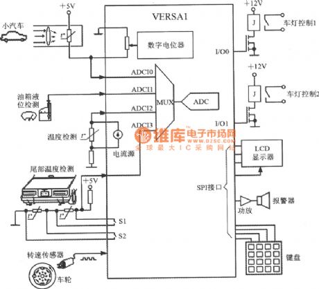
Automotive control system circuit diagram composed of VERSA1 monolithic data acquisition system with DSP function
(View)
View full Circuit Diagram | Comments | Reading(531)
Pressure and temperature control system circuit diagram composed of VERSA
Published:2011/5/5 0:54:00 Author:Ecco | Keyword: Pressure, temperature, control system

Pressure and temperature control system circuit diagram composed of VERSAmonolithic data acquisition system with DSP function
(View)
View full Circuit Diagram | Comments | Reading(847)
Temperature and gas concentration control system circuit diagram composed of VERSA1
Published:2011/5/5 0:56:00 Author:Ecco | Keyword: Temperature , gas , concentration , control system

Temperature and gas concentration control system circuit diagram composed of VERSA1 monolithic data acquisition system with DSP function
(View)
View full Circuit Diagram | Comments | Reading(1010)
TDA9187 picture quality improvement IC diagram
Published:2011/5/4 22:43:00 Author:Ecco | Keyword: picture quality, improvement, IC


TDA9187 is picture quality improvement IC produced by Philips, it is widely used in Changhong projection color TV series. 1. Features of functionTDA9187 integrated circuit includes pulse signal processing circuit, color saturation correction circuit, the luminance signal processing circuit, the definition improvement circuit, colour transient improvement circuit, the delay control circuit, color signal processing circuit, A / D converter, I2C bus control circuit. The block diagram of the circuit is shown in Figure 1. Figure 1 shows the block diagram of TDA9187 integrated circuit.
2. Pin functions and data TDA9187 integrated circuit uses 24-pin dual in-line package, the pin functions and data are listed in Table 1. Table 1 shows TDA9187 integrated circuit pin functions and data.
(View)
View full Circuit Diagram | Comments | Reading(550)
TDA9112-I2C bus control row / field scanning integrated circuit diagram
Published:2011/5/4 21:53:00 Author:Ecco | Keyword: bus control, row , field , scanning , integrated circuit


TDA9112 is the bus control row / field scanning integrated circuit produced by Philips, it is widely used in color displays, such as Tsinghua Tongfang series of color display. 1. Features of functionTDA9112 IC includes I2C bus interface circuit, the line oscillator circuit, field oscillation and the sawtooth wave generating circuit, left and right pincushion correction circuit, the line excitation circuit, PLL circuit, the same frequency signal processing circuit, ABL beam current system circuit, X-ray protection circuit, and other auxiliary functions circuit. 2. Pin functions and dataTDA9112 IC uses 32-pin dual in-line package, the pin functions and the number are shown in Table 1. Table 1 shows TDA9112 integrated circuit pin functions and data.
(View)
View full Circuit Diagram | Comments | Reading(459)
Camera Electronic Photometering System Circuit
Published:2011/5/4 22:52:00 Author:chopper | Keyword: Camera, Electronic, Photometering System

In the mid-range cameras,CdS photoresistor acts as aelectronic photometering component.When light reach the CdS photoresistor through the pore plate,move the density board to blance the circuit.And the even light sent out by two LEDs means optimum aeration.It meas underexposure or overexposure when one of the LEDs is brilliant while the other is dark.At this time,moving the density board would be a solution to get a optimum exposure. (View)
View full Circuit Diagram | Comments | Reading(698)
LA6510-geomagnetic correction output amplifier integrated circuit
Published:2011/5/4 22:44:00 Author:Nicole | Keyword: geomagnetic correction, output amplifier

LA6510 is a geomagnetic correction output amplifier integrated circuit which is produced by Sanyo, it is used as geomagnetic correction singal amplifier in new type large screen, large screen PIP and color TV.
1, Function and feature
LA6510 integrated circuit contains two-way same function amplifier circuit, reference voltage steady voltage setting circuit and other assist functional circuit.
2, Pin function and data
LA6510 integrated circuit adopts 10-pin package, the pin function and data of this integrated circuit is shown in chart1.
(View)
View full Circuit Diagram | Comments | Reading(798)
Capacitor fourth-order low-pass filter circuit diagram
Published:2011/5/4 22:42:00 Author:Rebekka | Keyword: Fourth-order low-pass capacitor filter

Capacitor fourth-order low-pass filter circuit is shown as below. The circuit uses an LM348 op amp four high-level low-pass filter circuit. For example, fc = 20KHz, filter transmission coefficient is Ho = 1, Q01 = 0.514, Q02 = 1.306. Because the count of band-pass amplification factor is the same with the four amplifiers. So it is enough to equip with a current source (LM334Z). You can have a precise adjustment by potentiometer RP. (View)
View full Circuit Diagram | Comments | Reading(1938)
Transformer Equivalent Circuit
Published:2011/5/4 21:59:00 Author:Robert | Keyword: Transformer, Equivalent

Transformer equivalent circuit is shown below.The approximate equivalent circuit can be used to calculate and analyze some issues of the transformer load operation, such as changes in the secondary side voltage of the parallel load distribution etc. which move the excitation branch to the end point. Little calculation error caused by calculation: the transformer's excitation current (which means the current with no load) is 2%-10% of the rated current. (Less than 1% for large transformer).
(View)
View full Circuit Diagram | Comments | Reading(938)
Kara OK Tone Circuit
Published:2011/5/4 9:27:00 Author:TaoXi | Keyword: Kara OK Tone

When we using Kara OK to enjoy ourselves, the singer always can't keep up the tunes because of the accompaniment tunes too high or too low. If we install this circuit in the Kara OK machine, so we can easily keep up the tunes. The figure is as shown, theinput signal from the terminal Lin is sendto the 7-pin of ICI voltage comparator, then the signal from 1-pin of ICI send to the 10-pin of the IC2 voice modulation integrated circuit (KD0071).At this moment, one signal return to ICl to compare with the input signal. Another signal send out by the pin-15 of IC2, and connect to the back-stage power amplifier. By adjusting the potentiometer RP between pin-8 and pin-9 of IC2, we can change the oscillation frequency of the circuit, then change the tone of output signal to produce modulation effect. When we are debugging,we need toplace the potentiometer RP in the middle of resistance, then adjust the resistance of resistor R6, R7, turn on/off the ground wire of P point (pin-5 IC2). If the potentiometer RP's resistance decreases, Tone will be low; If the potentiometer RP's resistance increases, Tone will be high.
(View)
View full Circuit Diagram | Comments | Reading(702)
| Pages:1956/2234 At 2019411942194319441945194619471948194919501951195219531954195519561957195819591960Under 20 |
Circuit Categories
power supply circuit
Amplifier Circuit
Basic Circuit
LED and Light Circuit
Sensor Circuit
Signal Processing
Electrical Equipment Circuit
Control Circuit
Remote Control Circuit
A/D-D/A Converter Circuit
Audio Circuit
Measuring and Test Circuit
Communication Circuit
Computer-Related Circuit
555 Circuit
Automotive Circuit
Repairing Circuit