
Circuit Diagram
Index 1939
4-20MA Current Transmitter Circuit with 5V Power
Published:2011/5/6 6:02:00 Author:Sue | Keyword: 4-20MA, Current, Transmitter, 5V Power

View full Circuit Diagram | Comments | Reading(768)
Transistor PK160F80 internal circuit
Published:2011/5/8 19:14:00 Author:Christina | Keyword: Transistor, internal circuit

The Transistor PK160F80 internal circuit is as shown:
(View)
View full Circuit Diagram | Comments | Reading(365)
Bicyle Bell Circuit (2)
Published:2011/5/8 6:45:00 Author:Robert | Keyword: Bicyle, Bell

The bicycle bell introduced in this example can give the sound of polite expressions: Please make way, thank you after pressing the control button. It can be used in bicyle or electric bicyle. The circuit's working principle is shown below. This bicyle bell circuit is made up be the voice circuit and audio amplification output circuit which is shown in the picture.The voice circuit is made up by the voltage integrated circuit IC1, resistance R1, saturation zener diode VS.The audio power amplification circuit is made up by capacitors C1~C3, resistance R2, audio power amplification integrated circuit IC2 and speaker BL.The +12V voltage from the battery not only supply the IC2 with its working voltage, but also supply IC1 with 3V DC working voltage through R2's current limiting and VS's voltage regulation.Pressing the control button to trigger the IC1 to work and its O/P port would output voice electrical signal. After the power amplification in IC2 this electrical signal would drive BL to give the voice sound Please make way, thank you .
IC1 uses the voice integrated circuit with saving the voice information of Please make way, thank you , such as HL-169A type etc. IC2 uses LM386 audio power amplification integrated circuit.
(View)
View full Circuit Diagram | Comments | Reading(728)
Pressure Sensor Signal Regulating Circuit
Published:2011/5/6 22:08:00 Author:Sue | Keyword: Pressure Sensor, Signal Regulating

*1% thin film resistor, T1 is sensor NPH-8-100AH. (View)
View full Circuit Diagram | Comments | Reading(676)
Music volume control (LF356) circuit
Published:2011/5/6 21:23:00 Author:TaoXi | Keyword: Music volume


The Music volume control (LF356) circuit is as shown. This circuit can be used in Kara OK audio equipment and it also can be used to control the microphone music volume automatically and weak the base music. FET T1 (2N3819) can be used as the variable resistor, R1 and T1 constitute the divider circuit, T1's equivalent resistance is controlled by the control voltage of T1's control gate, the gate control voltage is amplified and rectified, filtered by the audio signal. This control voltage changes with the input signal, and the partial pressure ratio of the input signal changes too, that changes the music signal components which are sent into the op amp inverting input port. This circuit uses the FET input-type integrated operational amplifier LF356. As the circuit is the inverse proportion operation, so the input resistance is small (less than 470kΩ), the half-power bandwidth is about 5Hz ~500kHz, the gain range is 0~-38dB, the input signal amplitude should not exceed 8Vp-p.
The main parameters of the integrated operational amplifier LF356 (typical):
(View)
View full Circuit Diagram | Comments | Reading(1584)
Electronic code lock circuit
Published:2011/5/8 19:01:00 Author:Christina | Keyword: Electronic, code lock

The electronic code lock circuit is as shown.
The ICl is the 5G058-specific lock integrated circuit 5G058, it's pin 1 to pin-6 connect the external key switches to the power positive supply, they are six valid input key, if you want to unlock it, you must comply with the order of Sl to S6; key switch S7 is the false key input port which is connected to pin-8, it is free to connect one or several keys into a keyboard; pin-9 is the key direction port, during each key connectivity, the LEDl will turn on to confirm that the key input is valid; pin-10 is the alarm output port, if you do not comply with the order of Sl to S6 or exceed the effective unlock time, pin-10 will output the high-level voltage to trigger the IC2 anti-burglar alarm language circuit SR8803A and make the speaker BL to issue the language warning. The effective unlock time is determined by the sizes of capacitor C1 and potentiometer RPl.
Figure . Electronic code lock circuit (View)
View full Circuit Diagram | Comments | Reading(1323)
2.1 channel active speaker circuit
Published:2011/5/6 21:48:00 Author:TaoXi | Keyword: 2.1 channel, active speaker

The 2.1 channel active speaker circuit is as shown:
(View)
View full Circuit Diagram | Comments | Reading(2479)
The Static Offset Circuit of the Triode Common-Emitter Amplifier
Published:2011/5/6 20:44:00 Author:Borg | Keyword: Static offset, Common-Emitter Amplifier

In the following figure, there is a circuit formed by static potentials and bias voltages of common-emitters(i.e V502,V504 and V506). When the supply voltage changes even a little, the static operating point will be effected, and the brightness on the screen will be effected because the static electrode potential of the output tube changes. Therefore, with this circuit, the bias voltage on the emitter of the amplifier changes synchronously with the supply power of +9V, i.e even when this supply power changes a little, the voltages on the emitters, V502,V504 and V506, will change subsequently, making sure that both of the common- and grounded- transistors won’t change because of the supply power, which means that the static potentials of V501,V503 AND V506 keep steady. This character can not only keep the consistence of piles of products, but also make the brightness of a singal screen not to be effected by the little changes of the supply power.
(View)
View full Circuit Diagram | Comments | Reading(492)
The Amplifier Circuit of Dually Amplified TV Antennas
Published:2011/5/6 20:50:00 Author:Borg | Keyword: Amplifier Circuit, Dually Amplified TV Antennas

The Amplifier Circuit of Dually Amplified TV Antennas (View)
View full Circuit Diagram | Comments | Reading(1964)
Current Transformer/CT
Published:2011/5/6 21:23:00 Author:Borg | Keyword: current transformer/CT
Our company produce more than 50 types of current transformers/CTs which are widely used in electron watt-hour meters, electricity transducers,digital electrical measuring instruments,intelligent instruments,intelligent switch cabinets,intelligent motor protectors,sampling precision testers, electric relays, electrical leakage protectors, power supervisory systems and automatic control systems, functioning as the separators,transmitters and transporters,etc.
We can produce CTs of all models according to customers’ need, and the prices are low. (View)
View full Circuit Diagram | Comments | Reading(408)
A Protection Circuit of Default Phases of Three-Phase Three-Wire Power Sources
Published:2011/5/7 19:48:00 Author:Borg | Keyword: Default Phases, Three-Phase, Three-Wire, Power Sources

The following is a circuit used toprotect the defult-phases of three-phase three-wire power sources. Without anyone of A,B or C, the electrical level (LEV) that the optical coupler output will be lower than the reference voltage that the inverting input node of the comparator holds, and the latter will low LEV to block the PWN driving signals, finally, the supply power will be shut down. Besides, if the input polar of the comparator changes, the PWM signals can also be blocked by high LEV. This circuit separates heavy currents by optocouplers, which is safe to use, while RP1 and RP2 are used to adjust the threshold values of the protecting behaviors. (View)
View full Circuit Diagram | Comments | Reading(797)
A Small-Scale Photoflash Circuit
Published:2011/5/7 19:58:00 Author:Borg | Keyword: Small-Scale, Photoflash Circuit

The following is a small-scale photoflash circuit, when it works, the two teams of micro bulbs will flash alternately.
(View)
View full Circuit Diagram | Comments | Reading(549)
The Control Circuit of Timing in Turn
Published:2011/5/7 20:13:00 Author:Borg | Keyword: Control Circuit, Timing, in Turn

This circuit can periodically control two switches in turn, the control time ranges from several seconds to dozens of seconds freely;when it is used a forward and reversely moving machine control, it can make the motor periodically move back and forward accordingly.
(View)
View full Circuit Diagram | Comments | Reading(621)
The Heating/Ventilation Circuit of the DPCA-Picasso Car
Published:2011/5/7 21:35:00 Author:Borg | Keyword: Heating/Ventilation Circuit, the DPCA-Picasso Car

The Heating/Ventilation Circuit of the DPCA-Picasso Car (View)
View full Circuit Diagram | Comments | Reading(533)
The Electrical System Circuit of the Citroen-Elysee Car
Published:2011/5/7 22:35:00 Author:Borg | Keyword: Electrical System, Citroen-Elysee

35-battery 50-power case 300-ignition switch 784-16:route diagnosis plugs 40-dashboard 145-airbag control unit 766-rotary switch 479-passenger seat belt pretensioners 478-driver seat belt pretensioner 884-driver airbag 885-passenger airbag 886-the neutral switch of passenger airbag CP-cablespositive CN-cables negative AN-mainbundle PB-panel bundle SC-airbag bundle
The Electrical System Circuit of the Citroen-Elysee Car (View)
View full Circuit Diagram | Comments | Reading(882)
The ABS Circuit of the Citroen-Elysee Car
Published:2011/5/8 9:42:00 Author:Borg | Keyword: ABS Circuit, Citroen-Elysee

The ABS Circuit of the Citroen-Elysee Car (View)
View full Circuit Diagram | Comments | Reading(950)
The Headlights Circuit of the Bluebird Car
Published:2011/5/8 9:46:00 Author:Borg | Keyword: Headlights, Bluebird
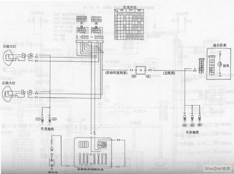
The Headlights Circuit of the Bluebird Car (View)
View full Circuit Diagram | Comments | Reading(597)
The Circuit of License Plate Lamps,Tail Lamps and Brake Lamps of the Bluebird Car
Published:2011/5/8 10:02:00 Author:Borg | Keyword: License Plate Lamps, Tail Lamps , Brake Lamps, Bluebird
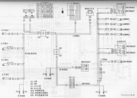
(A):Type A (B):Type B (C):Type L.H.D (D)Type R.H.D (KH):the type of Hongkong hardtop (NK):except the type of Hongkong hardtop (SP):the model with rear spoilers
The Circuit of License Plate Lamps,Tail Lamps and Brake Lamps of the Bluebird Car (View)
View full Circuit Diagram | Comments | Reading(716)
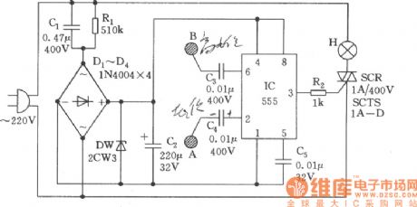
Lamp Touch Switch Circuit
Published:2011/5/6 2:11:00 Author:Sue | Keyword: Lamp, Touch, Switch
View full Circuit Diagram | Comments | Reading(646)
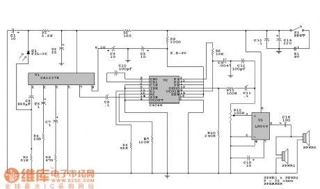
Principle of Audio Circuit
Published:2011/5/6 1:09:00 Author:Sue | Keyword: Principle, Audio Circuit
View full Circuit Diagram | Comments | Reading(661)
| Pages:1939/2234 At 2019211922192319241925192619271928192919301931193219331934193519361937193819391940Under 20 |
Circuit Categories
power supply circuit
Amplifier Circuit
Basic Circuit
LED and Light Circuit
Sensor Circuit
Signal Processing
Electrical Equipment Circuit
Control Circuit
Remote Control Circuit
A/D-D/A Converter Circuit
Audio Circuit
Measuring and Test Circuit
Communication Circuit
Computer-Related Circuit
555 Circuit
Automotive Circuit
Repairing Circuit