
Circuit Diagram
Index 1938
CMOS 555 Equivalent Functional Block Diagram Circuit
Published:2011/5/6 2:18:00 Author:Sue | Keyword: Equivalent, Functional Block Diagram

View full Circuit Diagram | Comments | Reading(639)
Phase shift sine wave oscillator circuit
Published:2011/5/8 19:56:00 Author:Christina | Keyword: Phase shift, sine wave, oscillator

The Phase shift sine wave oscillator circuit:
(View)
View full Circuit Diagram | Comments | Reading(1373)
Transistor PK130F80 internal circuit
Published:2011/5/8 19:18:00 Author:Christina | Keyword: Transistor, internal circuit

The Transistor PK130F80 internal circuit is as shown:
(View)
View full Circuit Diagram | Comments | Reading(403)
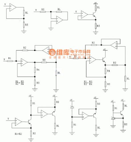
Mass V-I Converting Circuit
Published:2011/5/6 21:36:00 Author:Sue | Keyword: Mass, V-I, Converting
View full Circuit Diagram | Comments | Reading(551)
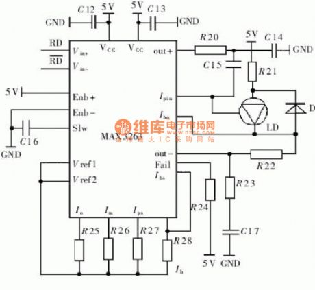
Modulation Driving Circuit
Published:2011/5/6 21:43:00 Author:Sue | Keyword: Modulation, Driving
View full Circuit Diagram | Comments | Reading(607)
Simple and stable sine wave generator circuit
Published:2011/5/8 19:36:00 Author:Christina | Keyword: Simple, stable, sine wave, generator

The Simple and stable sine wave generator circuit is as shown:
(View)
View full Circuit Diagram | Comments | Reading(608)
Snore Sensing Circuit
Published:2011/5/6 6:11:00 Author:Sue | Keyword: Snore, Sensing

View full Circuit Diagram | Comments | Reading(516)
Xiling brand BCD-182W refrigeration & Frozen fridge circuit
Published:2011/5/8 19:40:00 Author:Christina | Keyword: Xiling brand, Frozen, refrigeration, fridge

The Xiling brand BCD-182W refrigeration & Frozen fridge circuit is as shown:
(View)
View full Circuit Diagram | Comments | Reading(545)
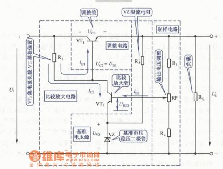
Voltage Stabilizing Circuit with Amplifying Transistor
Published:2011/5/6 6:13:00 Author:Sue | Keyword: Voltage Stabilizing, Amplifying Transistor
View full Circuit Diagram | Comments | Reading(518)
Resistance tolerance measurement circuit
Published:2011/5/8 19:35:00 Author:Christina | Keyword: Resistance tolerance, measurement

View full Circuit Diagram | Comments | Reading(498)
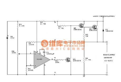
Principle of 60V Circuit
Published:2011/5/6 0:54:00 Author:Sue | Keyword: Principle, 60V
View full Circuit Diagram | Comments | Reading(561)
Transistor PK160F120 internal circuit
Published:2011/5/8 19:17:00 Author:Christina | Keyword: Transistor, internal circuit

The Transistor PK160F120 internal circuit is as shown:
(View)
View full Circuit Diagram | Comments | Reading(366)
Logic probe circuit
Published:2011/5/8 19:34:00 Author:Christina | Keyword: Logic, probe

The permanently connected LED is used to indicate the TTL voltage level and the changes of this level. If the LED-1 turns on, it means the input voltage is TTL high-level voltage, If the LED-1 turns off, it means the input voltage is TTL low-level voltage. When the input voltage level changes, LED-2 lights one time. This circuit can check the voltage level, the level jump, the single pulse and the cluster pulse. Only half of each IC has used, so you need, you can use the same number of ICs as the two test probes. The in-phase driver of the monostable IC9602 is composed of the la and lc. This monostable in-phase driver IC9602 is triggered by the positive edge and negative edge of C1 and D1. If the cluster pulse's period is less than the width of the flash pulse, the edge LED-2 will always light.
(View)
View full Circuit Diagram | Comments | Reading(5)
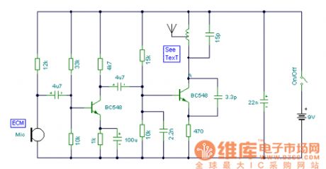
Simplified Radio Frequency Circuit
Published:2011/5/6 2:40:00 Author:Sue | Keyword: Simplified, Radio Frequency
View full Circuit Diagram | Comments | Reading(692)
Single Supply RTD Amplifying Circuit
Published:2011/5/6 6:02:00 Author:Sue | Keyword: Single Supply, RTD, Amplifying
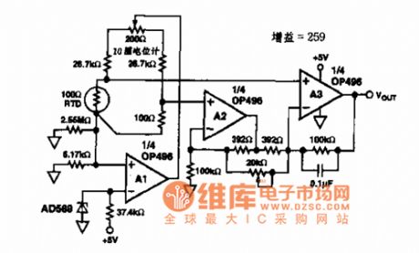
Sensor and OP196/296/496 type battery positive/negative input/output operational amplifier circuit.
Application: It is used in sensor adjustment, small power control, small-sized apparatus, battery monitoring and so on.
(View)
View full Circuit Diagram | Comments | Reading(1400)
Transistor PK160F160 internal circuit
Published:2011/5/8 19:16:00 Author:Christina | Keyword: Transistor, internal circuit

The Transistor PK160F160 internal circuit is as shown:
(View)
View full Circuit Diagram | Comments | Reading(366)
Digital frequency meter course design circuit
Published:2011/5/8 19:19:00 Author:Christina | Keyword: Digital frequency meter, course design

Figure. The digital frequency meter course design circuit (View)
View full Circuit Diagram | Comments | Reading(1719)
Precise Voltage And Current Transmitter Circuit
Published:2011/5/6 3:24:00 Author:Sue | Keyword: Precise, Voltage, Current, Transmitter
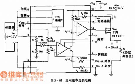
Application: It is used in pressure and temperature transmitter, industrial process control and so on.
Figure 3-62 Application Basic Junction Circuit
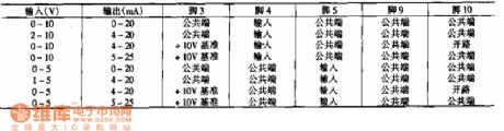
Basic Junction Circuit sensor inputs a voltage of 0-10V and outputs a current of 4-20mA. As seen in the figure below is the relation between variation range of input voltage, output current and pin.
(View)
View full Circuit Diagram | Comments | Reading(750)
Circuit measurement circuit with the range of 100nA-1mA
Published:2011/5/8 19:15:00 Author:Christina | Keyword: Circuit measurement, 100nA-1mA

View full Circuit Diagram | Comments | Reading(425)
Digital voltmeter signal circuit
Published:2011/5/8 19:13:00 Author:Christina | Keyword: Digital voltmeter, signal circuit

View full Circuit Diagram | Comments | Reading(537)
| Pages:1938/2234 At 2019211922192319241925192619271928192919301931193219331934193519361937193819391940Under 20 |
Circuit Categories
power supply circuit
Amplifier Circuit
Basic Circuit
LED and Light Circuit
Sensor Circuit
Signal Processing
Electrical Equipment Circuit
Control Circuit
Remote Control Circuit
A/D-D/A Converter Circuit
Audio Circuit
Measuring and Test Circuit
Communication Circuit
Computer-Related Circuit
555 Circuit
Automotive Circuit
Repairing Circuit