Circuit Diagram
Index 1931
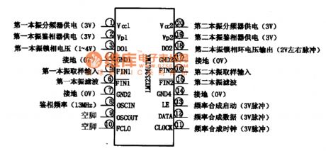
LMX2336LTMX-frequency synthesizer integrated circuit diagram
Published:2011/5/9 1:33:00 Author:Nicole | Keyword: frequency synthesizer

LMX2336LTMX is a frequency synthesizer integrated circuit which is produced by National Semiconductor Corporation, it is widely used in Samsung GSM telephone circuit, such as SGH6O0C、SGH800.
1. functions and features
LMX2336LTMX integrated circuit contains the first, second local oscillator frequency divider circuit, phase-locked loop frequency synthesis start-up circuit, phase-locked loop frequency synthesis data circuit, phase-locked loop frequency synthesis color circuit and other assistant functions circuits.
2. pin function and data
LMX2336LTMX integrated circuit adopts 20-foot dual in-line package, the pin arrangement and pin function and data is shown in the figure1. This IC and LMX2336LTMX can be used interchangeably.
(View)
View full Circuit Diagram | Comments | Reading(559)
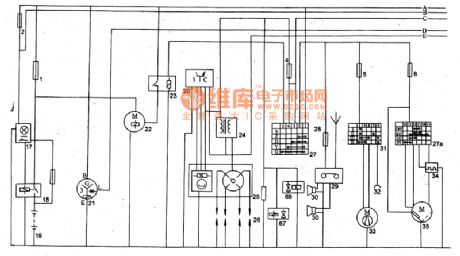
The basic circuit diagram of Shenyang JinBei power supply, start-up, ignition, car heater, wiper
Published:2011/5/9 0:25:00 Author:Nicole | Keyword: Shenyang JinBei, power supply, start-up, ignition, car heater, wiper

The basic circuit diagram of Shenyang JinBei SY6474、SY6475A、SY6475 series light bus circuit, power supply, start-up, ignition, car heater, wiper
16-fuse; 17-storage battery control switch and indicator light; 18-storage battery switch; 19-storage battery; 20-firing controller; 21-integral alternator; 22-starter; 23-starter relay; 24-ignition coil; 25-Hall non-contact distributor; 26-spark plug; 27-ignition switch; 27a-wiper switch; 28-radio fuse; 29-radio; 30-loudspeaker; 31-heater motor switch; 32-connector; 33-heater motor; 34-wiper interval relay;35-wiper motor; 67-electromagnetic valve; 69-electromagnetic valve. (View)
View full Circuit Diagram | Comments | Reading(2215)
M5218AP-operational amplifier integrated circuit diagram
Published:2011/5/9 1:10:00 Author:Nicole | Keyword: operational amplifier

M5218AP is a common operational amplifier integrated circuit which is produced by Mitsubishi Corp, it is widely used in large screen and other screen color television, audio system, computer and its diaplay and all kinds of electric appliances electronic control circuit.
1. functions and features
M5218AP integrated circuit contains two ways operational amplifier with same functions.
2. pin function and data
M5218AP integrated circuit adopts 8-foot dual in-line package, it is applied to ChangHong CN一15 movement color television, the pin function and data of this integrated circuit is shown in the table1.
(View)
View full Circuit Diagram | Comments | Reading(611)
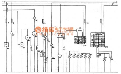
Shenyang JinBei SY6474、SY6475A、SY6475 series light bus instrument, singal, headlamp circuit diagram
Published:2011/5/8 22:49:00 Author:Nicole | Keyword: Shenyang JinBei, light bus, instrument, singal, headlamp

36-cigar lighter; 37-work light socket; 38-charging indicator light; 39-motor tachometer; 40-water temperature gauge; 41-water temperature gauge sensor; 42-fuel meter; 43-fuel meter sensor; 44-oil pressure alarm lamp; 45-oil pressure alarm switch; 46-hand brake indicator light; 47-hand brake constant switch; 48-LED; 49-braking pressure alarm lamp; 49a-raking pressure alarm switch; 51-side speaker relay; 51-speaker; 52-speaker button; 53-turning flashing relay; 54-left steer singal light; 55-left steer indicator light; 56-right steer indicator light; 57-right steer singal light; 27b-steering signal and danger signal; 27c-headlamp change beam and lighting switch; 58-headlamp; 59-upper beam indicator light. (View)
View full Circuit Diagram | Comments | Reading(970)
The Engine Coolant Temperature Circuit of the DPCA-Picasso 2.0L Car
Published:2011/5/8 23:29:00 Author:Borg | Keyword: Engine, Coolant Temperature Circuit, the DPCA-Picasso 2.0L Car

The Engine Coolant Temperature Circuit of the DPCA-Picasso 2.0L Car (View)
View full Circuit Diagram | Comments | Reading(798)
LC5872-system control microcomputer integrated circuit diagram
Published:2011/5/6 2:56:00 Author:Nicole | Keyword: system control, microcomputer


LC5872 is a system control microcomputer integrated circuit which is produced by Sanyo, it is widely used in low voltage walkman and other audio equipments.
1, functions and features
LC5872 integrated circuit contains LCD display drive control circuit, key switch compiling code circuit, all kinds of control functions load drive control circuit, memory circuit, address singal process circuit, motor control circuit, record indicator light drive control circuit, radio circuit power supply on/off control circuit, counter reset circuit, clock oscillation circuit, record/play switching control circuit and other assistant functions circuits.
2, pin function and data
LC5872 integrated circuit adopts 80-foot flat type package, the pin function and data of this integrated circuit is shown in the table1.
(View)
View full Circuit Diagram | Comments | Reading(867)
The Engine Cooling System Circuit of the DPCA-Picasso 2.0L Car
Published:2011/5/8 23:28:00 Author:Borg | Keyword: Engine, Cooling System Circuit, the DPCA-Picasso 2.0L Car

The Engine Cooling System Circuit of the DPCA-Picasso 2.0L Car (View)
View full Circuit Diagram | Comments | Reading(588)
The Engine Jet/Ignition Circuit of the DPCA-Picasso 2.0L Car
Published:2011/5/8 23:26:00 Author:Borg | Keyword: Engine, Jet/Ignition Circuit, the DPCA-Picasso 2.0L Car

The Engine Jet/Ignition Circuit of the DPCA-Picasso 2.0L Car (View)
View full Circuit Diagram | Comments | Reading(568)
The Alerter Circuit of the Bluebird Car
Published:2011/5/9 2:20:00 Author:Borg | Keyword: Alerter Circuit, Bluebird

The Alerter Circuit of the Bluebird Car (View)
View full Circuit Diagram | Comments | Reading(704)
Hall device series connection drive circuit diagram
Published:2011/5/6 2:26:00 Author:Nicole | Keyword: Hall device, series connection

The figurea is a hall device series connection drive circuit. Hall device's magnetoresistance effect produces error. In the circuit, it adopts the method of H1, H2, H3 hall devices series connection, it eliminates the error which is produced by magnetoresistance effect by adding negative feedback. The thermal resistor RT which is connected to feedback circuit is used to improve the circuit's temprature characteristice. S1 and S2 are used in the input motor's turn speed control singal.
(View)
View full Circuit Diagram | Comments | Reading(661)
The Speedometer,Tachometer and Fuel Gauge Circuit of the Bluebird Car
Published:2011/5/9 2:19:00 Author:Borg | Keyword: Speedometer, Tachometer, Fuel Gauge Circuit

The Speedometer,Tachometer and Fuel Gauge Circuit of the Bluebird Car (View)
View full Circuit Diagram | Comments | Reading(1315)
The Signal Light and Hazard Warning Lantern Circuit of the Bluebird Car
Published:2011/5/9 2:18:00 Author:Borg | Keyword: Signal Light, Hazard Warning Lantern, Bluebird

The Signal Light and Hazard Warning Lantern Circuit of the Bluebird Car (View)
View full Circuit Diagram | Comments | Reading(858)
The Fog Lamp Circuit of the Car
Published:2011/5/9 2:17:00 Author:Borg | Keyword: Fog Lamp, Bluebird

The Fog Lamp Circuit of the Bluebird Car (View)
View full Circuit Diagram | Comments | Reading(659)
The Reversing Light Circuit of the Bluebird Car
Published:2011/5/8 23:25:00 Author:Borg | Keyword: Reversing Light, Bluebird

(AT):type A/T (MT): type M/T (A):the type with A/T indicators (B):the type without indicators
The Reversing Light Circuit of the Bluebird Car
(View)
View full Circuit Diagram | Comments | Reading(595)
The No.2 Automatic Transmission (AT) Circuit of the Bluebird Car
Published:2011/5/9 2:47:00 Author:Borg | Keyword: Automatic Transmission, Bluebird

The No.2 Automatic Transmission (AT) Circuit of the Bluebird Car (View)
View full Circuit Diagram | Comments | Reading(692)
LAC673-single chip stereo paly integrated circuit diagram
Published:2011/5/9 2:42:00 Author:Nicole | Keyword: single chip, stereo, play


LAC673 is a single chip stereo paly integrated circuit which is produced by MITSVMI, it is widely used in import radio walkman.
1. LAC673 internal block and pin function
LAC673 integrated circuit contains double preamplifier, double power amplifier, DC electronic volume control circuit, DC motor steady speed circuit. The internal circuit block diagram of this integrated block is shown in the figure1. This IC adopts dual flat type package, the pin function and data of this integrated circuit is shown in the table1.
2. LAC673 typical application circuit
Because LAC673 integrated block is functionally complete, it can form a stereo tape player circuit with a LAC673, if adding a stereo tuner then it can form a stereo radio player circuit. The typical application circuit of LAC673 integrated block is shown in the figure1.
The figure1 is the internal circuit block diagram of LAC673 integrated block
The table1 is the pin function and data of LAC673 integrated circuit
The figure1 is the typical application circuit of LAC673 integrated block
(View)
View full Circuit Diagram | Comments | Reading(1049)
The typical application circuit diagram of LC7480 IC
Published:2011/5/6 3:33:00 Author:Ecco | Keyword: typical application circuit , IC

The typical application circuit
The typical application circuit of LC7480 IC using in Changhong NC-3 series of picture in picture large screen color TV is shown as the chart. Tip: LC7480 IC is used for the sub-storage compression of Y, (R-Y), (B-Y) into serial Y (R-Y), (B-Y) screen digital signal.
The typical application circuit diagram of LC7480 IC is shown as the chart. (View)
View full Circuit Diagram | Comments | Reading(810)
The typical application circuit diagram of LC7582 IC
Published:2011/5/6 3:39:00 Author:Ecco | Keyword: typical application circuit , IC

The typical application circuit
The display driver typical application circuit composed of LC7582 IC and SL一20110 display is shown as the chart.
The typical application circuit diagram of LC7582 IC is shown as the chart. (View)
View full Circuit Diagram | Comments | Reading(3180)
KA2209-dual track power amplifier integrated circuit diagram
Published:2011/5/6 8:06:00 Author:Nicole | Keyword: dual track, power amplifier

KA2209 is a dual track power amplifier integrated circuit which is produced by South Korea's Samsung, it is widely used in all kinds of low voltage walkman, repeater, multimedia audio, mini speaker and other sound equipments.
1, functions and features
KA2209 integrated circuit contains two-way same function audio frequency power pre-amplifier, audio frequency power amplifier circuit and some other assistant function circuits.
2, pin function and data
KA2209 integrated circuit adopts 8-foot dual in-line package, the pin function and data of this integrated circuit is shown in the table 1-1.
Indication: Whether the ①, ② foot voltage of KA2209 is 1/2 of VCC or not, it is an important basis to decide whether IC is normal.
(View)
View full Circuit Diagram | Comments | Reading(963)
MC-2 capacitive humidity sensor application circuit
Published:2011/5/6 2:19:00 Author:Ecco | Keyword: capacitive, humidity , sensor, application circuit

MC-2 capacitive humidity sensor application circuit
(View)
View full Circuit Diagram | Comments | Reading(1630)
| Pages:1931/2234 At 2019211922192319241925192619271928192919301931193219331934193519361937193819391940Under 20 |
Circuit Categories
power supply circuit
Amplifier Circuit
Basic Circuit
LED and Light Circuit
Sensor Circuit
Signal Processing
Electrical Equipment Circuit
Control Circuit
Remote Control Circuit
A/D-D/A Converter Circuit
Audio Circuit
Measuring and Test Circuit
Communication Circuit
Computer-Related Circuit
555 Circuit
Automotive Circuit
Repairing Circuit