
Circuit Diagram
Index 1922
Low-voltage Automatic Switching Circuit
Published:2011/5/7 3:02:00 Author:Joyce | Keyword: Low-voltage, Automatic, Switching

Low-voltage Automatic Switching Circuit is shown in the graph below.When the electric supply of 220V is depressurized by transformer T, VDw will breakdown thus making VT1 breakover and VT2 cut off.Meanwhile,the solid-state relay SSR will shutoff.At this time, after being bridge rectified by VD2 ~ VD5 andfiltered by C2.C3,it will output about 14V dc voltage. When the input ac voltage is 110V, after being depressurized by T, it is insufficient to breakdown VDw,so VT2 will breakover and VT1 will cutoff and SSR will be connected. At this moment, SSR, VD2 ~ VD3 and C2 、C3 will constitute a voltage doubling circuit ,which still output about 14V dc voltage. And the LED indicator light will be on.
(View)
View full Circuit Diagram | Comments | Reading(602)
555 IC automatic battery charger circuit diagram(1)
Published:2011/5/9 20:38:00 Author:Ecco | Keyword: 555 , IC , automatic , battery charger
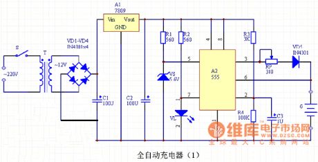
Automatic nickel-cadmium battery charger circuit is shown as the chart, the charger is mainly composed of the power supply circuit, voltage comparator and indicating circuit. The power supply is stepped-down by the T transformer, rectified by diodes VD1 ~ VD4, stabilized by three-terminal voltage regulator Manifold A1 and filtered by capacitors C1, C2, then the circuit can output stable 9V DC voltage for the charger. Voltage comparator is composed of A2 time base circuit, and it has a Zener diode VS (stable voltage 5.6V) connected to pin 5 of the control side, so the reset level of the circuit will be located in the 5.6V. VL LED is the charging indicator. A1 selects LM7809 three-terminal voltage regulator Manifold, and it should be installed aluminum heat sink. VD1 ~ VD5 use IN4001 silicon rectifier diodes. VS selects 5.6V, 1/2W Zener diode, such as UZ-5.6B, IN5232. VL uses an ordinary red LED. RP selects 2W wirewound potentiometer, R1 ~ R4 are select 1/8W carbon film resistors. C1 selects CD11-25V aluminum electrolytic capacitor, C2, C3 are the CD11-16V aluminum electrolytic capacitors. S uses an ordinary small 1 × 1 power switch. T uses 220V/12V, 5VA small, high quality power transformer.
(View)
View full Circuit Diagram | Comments | Reading(4451)
The temperature indicator circuit diagram composed of MAX139
Published:2011/5/9 21:35:00 Author:Ecco | Keyword: temperature indicator

The temperature indicator circuit diagram composed of MAX139 is shown as the chart.
(View)
View full Circuit Diagram | Comments | Reading(2094)
Fiat Palio motor circuit diagram
Published:2011/5/9 21:18:00 Author:Ecco | Keyword: Fiat Palio, motor


View full Circuit Diagram | Comments | Reading(3987)
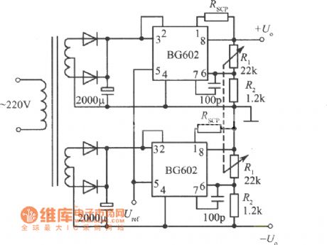
Positive and negative output voltage integrated regulated power supply (BG602) circuit diagram
Published:2011/5/9 21:21:00 Author:Ecco | Keyword: Positive , negative , output voltage , integrated , regulated power supply
View full Circuit Diagram | Comments | Reading(572)
Relay-composed Start-up Circuit
Published:2011/5/7 3:23:00 Author:Joyce | Keyword: Relay-composed, Start-up

Relay-composed Start-up Circuit is shown in the graph below. In the input end of the power ,resistance R is connected.R has two functions.the first oneis that it can prevent impluse current on the large capacitance C1 in starting up,which wouldimpact the poweritself;the second one is to prolong the time when the load is receiving the electric supply. In this process, because the voltage of the relay J in the output end is less than 12 V ,the actuation voltage, R will be connected to the circuit to limit the current and depressurize the voltage.As the charging of C1, C3 completes, relay J contacts and actuates to short-circuit R. At this moment, power supply will function properly.
(View)
View full Circuit Diagram | Comments | Reading(458)
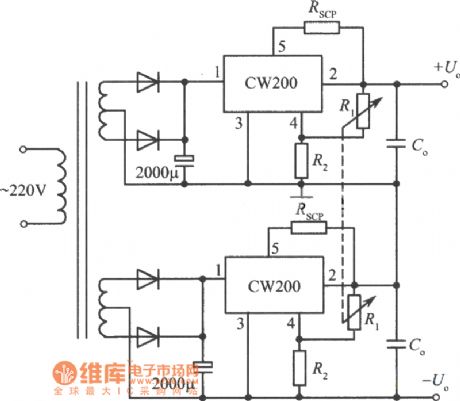
Positive and negative output voltage integrated regulated power supply (CW200) circuit diagram
Published:2011/5/9 21:22:00 Author:Ecco | Keyword: Positive , negative , output , voltage , integrated , regulated power supply
View full Circuit Diagram | Comments | Reading(512)
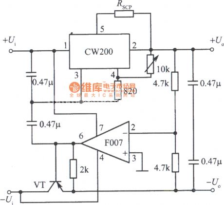
Tracking integrated regulated power supply (CW200) circuit diagram
Published:2011/5/9 21:24:00 Author:Ecco | Keyword: Tracking , integrated , regulated power supply
View full Circuit Diagram | Comments | Reading(539)
QS5K2 Internal Circuit
Published:2011/5/9 21:40:00 Author:Sharon | Keyword: Internal

QS5K2 Internal Circuit is shown below:
(View)
View full Circuit Diagram | Comments | Reading(478)
Chip diode appearance circuit diagram
Published:2011/5/9 21:41:00 Author:Ecco | Keyword: Chip diode , appearance

Chip diode appearance circuit diagram is shown as the chart.
The chip diode has many different types such as the rectifier diode, varactor diode, fast recovery diode, switching diode, zener diode, light emitting diode and transient voltage suppression diode. Most models of the chip diodes use the model of leading diode, some manufacturers also have their own requiring model, There is no uniform requirements.
(View)
View full Circuit Diagram | Comments | Reading(585)
S13050 5V V terminal voltage regulator integrated circuit diagram
Published:2011/5/9 21:47:00 Author:Ecco | Keyword: 5V , V terminal, voltage regulator , integrated circuit
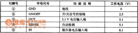
S13050 is 5V V terminal voltage regulator integrated circuit produced by American Microsystems, it is widely used in DVD players, televisions, computer monitors, sound system and various kinds of small household appliances, such as in the regulator circuit. 1. Features of functionS13050 contains +5 V voltage regulator integrated circuit, voltage regulator on / off control circuit, automatic detection circuit, and other ancillary functions circuit. 2. Pin functions and data S13050 integrated circuit uses 5-foot single package, the pin functions and data are listed in Table. S13050 IC pin functions and data
(View)
View full Circuit Diagram | Comments | Reading(580)
Single Display DATAS CH-7423 Power Supply Circuit
Published:2011/5/9 21:36:00 Author:Sharon | Keyword: Single Display, Power Supply
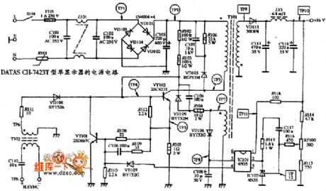
Single Display DATAS CH-7423 Power Supply Circuit is shown below:
(View)
View full Circuit Diagram | Comments | Reading(560)
TMP87CM36N monolithic microcomputer integrated circuit
Published:2011/5/8 21:47:00 Author:Ecco | Keyword: monolithic, microcomputer , integrated circuit


TMP87CM36N is the single-chip microcomputer integrated circuit produced by Toshiba, it is widely used in Changhong, Toshiba series of movement and assembly of large-screen color TV. 1. Features of functionsTMP87CM36N integrated circuits is mainly composed of the central processing (CPU), clock oscillator circuit, the reset control circuit, I2C bus control circuit, remote control command signals processing circuit, the character generation and processing circuit, the switch control power conversion circuit, keyboard scan decoding circuit, squelch control circuit, audio format conversion circuit, and other control and auxiliary functions circuit, its block diagram is shown in Figure 1.Figure 1 shows the circuit block diagram and pin functions and signal flowing of TMP87CM36N integrated.2. Pin functions and data TMP87CM36N integrated circuit uses the package with 42 feet in double rows, the pin functions and signal flowing are shown in Figure 1, the pin letter code and data are listed in Table 1. Table 1 shows TMP87CM36N pins letter code and data of integrated circuit.
(View)
View full Circuit Diagram | Comments | Reading(680)
TMP8TCK38N monolithic microcomputer integrated circuit
Published:2011/5/8 21:51:00 Author:Ecco | Keyword: monolithic, microcomputer, integrated circuit


TMP8TCK38N is the single-chip microcomputer integrated circuit produced by Toshiba, it is widely used in Changhong, Toshiba series of movement and assembly of large-screen color TV. 1. Features of functionsTMP8TCK38N integrated circuits is mainly composed of the central processing (CPU), clock oscillator circuit, the reset control circuit, I2C bus control circuit, remote control command signals processing circuit, the character generation and processing circuit, the switch control power conversion circuit, keyboard scan decoding circuit, squelch control circuit, audio format conversion circuit, and other control and auxiliary functions circuit, its block diagram is shown in Figure 1.Figure 1 shows the circuit block diagram and pin functions and signal flowing of TMP8TCK38N integrated.2. Pin functions and data TMP8TCK38N integrated circuit uses the package with 42 feet in double rows, the pin functions and signal flowing are shown in Figure 1, the pin letter code and data are listed in Table 1. Table 1 shows TMP8TCK38N pins letter code and data of integrated circuit.
(View)
View full Circuit Diagram | Comments | Reading(564)
TMP87CK36N monolithic microcomputer integrated circuit diagram
Published:2011/5/8 22:25:00 Author:Ecco | Keyword: monolithic , microcomputer, integrated circuit


TMP87CK36N is the single-chip microcomputer integrated circuit produced by Toshiba, it is widely used in Changhong, Toshiba series of movement and assembly of large-screen color TV. 1. Features of functionsTMP87CK36N integrated circuits is mainly composed of the central processing (CPU), clock oscillator circuit, the reset control circuit, I2C bus control circuit, remote control command signals processing circuit, the character generation and processing circuit, standby / on control circuit, keyboard scan decoding circuit, squelch control circuit, audio format conversion circuit, and other control and auxiliary functions circuit, its block diagram is shown in Figure 1.Figure 1 shows the circuit block diagram and pin functions and signal flowing of TMP87CK36N integrated.2. Pin functions and data TMP87CK36N integrated circuit uses the package with 42 feet in double rows, the pin functions and signal flowing are shown in Figure 1, the pin letter code and data are listed in Table 1.
(View)
View full Circuit Diagram | Comments | Reading(779)
QS5U12,QS5U13 Internal Circuit
Published:2011/5/9 21:30:00 Author:Sharon | Keyword: Internal

QS5U12,QS5U13 Internal Circuit is shown below:
(View)
View full Circuit Diagram | Comments | Reading(430)
T0P2O2YA1 PWM monolithic integrated circuit diagram
Published:2011/5/9 1:37:00 Author:Ecco | Keyword: PWM , monolithic , integrated circuit


T0P2O2YA1 is the PWM monolithic switching power supply integrated circuit which is manufactured by the Power Company in the United States, it is widely used in switching power supply circuit of DVD, VCD, etc. DVD players, computers and monitors, air conditioner control system and various other household appliances. 1. pin functions and data T0P2O2YA1 IC uses separate three-pin package, the pin functions and data are listed in Table. T0P223Y integrated circuit pin functions and data 2. The typical application circuit The block diagram of T0P2O2YA1 integrated circuit and typical application circuit are shown as the chart. The block diagram and typical application circuit of T0P2O2YA1 IC
(View)
View full Circuit Diagram | Comments | Reading(1142)
TMP87CH33N monolithic microcomputer integrated circuit diagram
Published:2011/5/9 1:08:00 Author:Ecco | Keyword: monolithic, microcomputer , integrated circuit
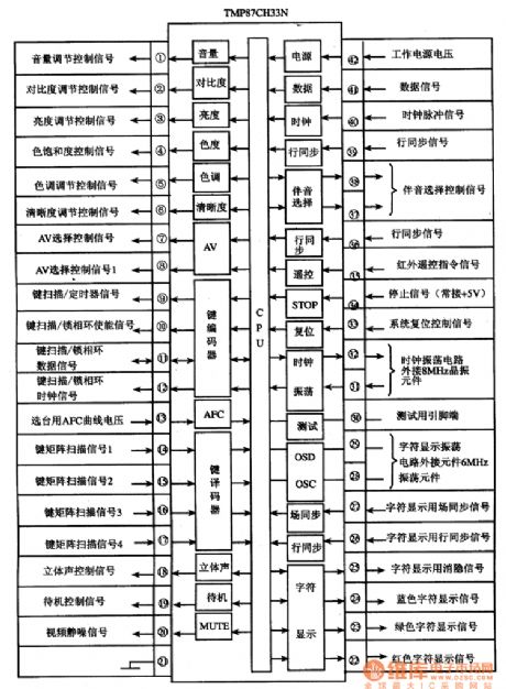
TMP87CH33N is the single-chip microcomputer integrated circuit produced by Toshiba, it is widely used in Toshiba, Konka series of movement and assembly of large-screen color TV.
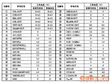
TMP87CH33N integrated circuit uses the plastic package with 42 feet in double rows, the pin functions and signal flowing are shown in Figure 1, the pin letter code and data are listed in Table 1.
(View)
View full Circuit Diagram | Comments | Reading(1428)
TMS34541NL-R digital clock integrated circuit diagram
Published:2011/5/9 2:07:00 Author:Ecco | Keyword: digital clock , integrated circuit


TMS34541NL-R is the digital clock integrated circuit produced by Toshiba, it is widely used in various digital clock. 1. Features of functionsTMS34541NL-R IC is mainly composed of the internal clock oscillator circuit, divider circuit, time control circuit, the comparator circuit and the fluorescent tube display output decoder and driver circuit. 2. Pin functionsTMS34541NL-R IC uses 28-pin dual in-line package, the pin functions are shown as the chart. 3. The typical application circuit The typical application circuit composed of TMS3451NL-R integrated circuit is shown as the chart.
(View)
View full Circuit Diagram | Comments | Reading(2221)
TMP87C766 monolithic microcomputer integrated circuit diagram
Published:2011/5/9 1:05:00 Author:Ecco | Keyword: monolithic , microcomputer integrated circuit


TMP87C766 is the single-chip microcomputer integrated circuit produced by Toshiba, it is widely used in Changhong, Konka, TCL series of movement and assembly of large-screen color TV. 1. Features of functionsTMP87C766 integrated circuits is mainly composed of the central processing (CPU), clock oscillator circuit, reset control circuit, I2C bus control circuit, key scan decoding circuit, the character display circuit,memory control circuitry, input / output (I / O) interface circuit, the clock oscillation circuit, the characters display the clock circuit, and other auxiliary functions circuit.2. Pin functions and data TMP87C766 integrated circuit uses the plastic package with 42 feet in double rows, the pin functions and signal flowing are shown in Figure 1, the pin letter code and data are listed in Table 1.
(View)
View full Circuit Diagram | Comments | Reading(568)
| Pages:1922/2234 At 2019211922192319241925192619271928192919301931193219331934193519361937193819391940Under 20 |
Circuit Categories
power supply circuit
Amplifier Circuit
Basic Circuit
LED and Light Circuit
Sensor Circuit
Signal Processing
Electrical Equipment Circuit
Control Circuit
Remote Control Circuit
A/D-D/A Converter Circuit
Audio Circuit
Measuring and Test Circuit
Communication Circuit
Computer-Related Circuit
555 Circuit
Automotive Circuit
Repairing Circuit