555 Circuit
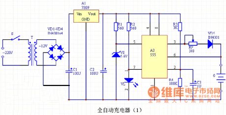
555 IC automatic battery charger circuit diagram(1)
Published:2011/5/9 20:38:00 Author:Ecco | Keyword: 555 , IC , automatic , battery charger | From:SeekIC

Automatic nickel-cadmium battery charger circuit is shown as the chart, the charger is mainly composed of the power supply circuit, voltage comparator and indicating circuit. The power supply is stepped-down by the T transformer, rectified by diodes VD1 ~ VD4, stabilized by three-terminal voltage regulator Manifold A1 and filtered by capacitors C1, C2, then the circuit can output stable 9V DC voltage for the charger. Voltage comparator is composed of A2 time base circuit, and it has a Zener diode VS (stable voltage 5.6V) connected to pin 5 of the control side, so the reset level of the circuit will be located in the 5.6V. VL LED is the charging indicator. A1 selects LM7809 three-terminal voltage regulator Manifold, and it should be installed aluminum heat sink. VD1 ~ VD5 use IN4001 silicon rectifier diodes. VS selects 5.6V, 1/2W Zener diode, such as UZ-5.6B, IN5232. VL uses an ordinary red LED. RP selects 2W wirewound potentiometer, R1 ~ R4 are select 1/8W carbon film resistors. C1 selects CD11-25V aluminum electrolytic capacitor, C2, C3 are the CD11-16V aluminum electrolytic capacitors. S uses an ordinary small 1 × 1 power switch. T uses 220V/12V, 5VA small, high quality power transformer.
Reprinted Url Of This Article:
http://www.seekic.com/circuit_diagram/555_Circuit/555_IC_automatic_battery_charger_circuit_diagram1.html
Print this Page | Comments | Reading(3)

Article Categories
power supply circuit
Amplifier Circuit
Basic Circuit
LED and Light Circuit
Sensor Circuit
Signal Processing
Electrical Equipment Circuit
Control Circuit
Remote Control Circuit
A/D-D/A Converter Circuit
Audio Circuit
Measuring and Test Circuit
Communication Circuit
Computer-Related Circuit
555 Circuit
Automotive Circuit
Repairing Circuit
Code: