
Circuit Diagram
Index 1927
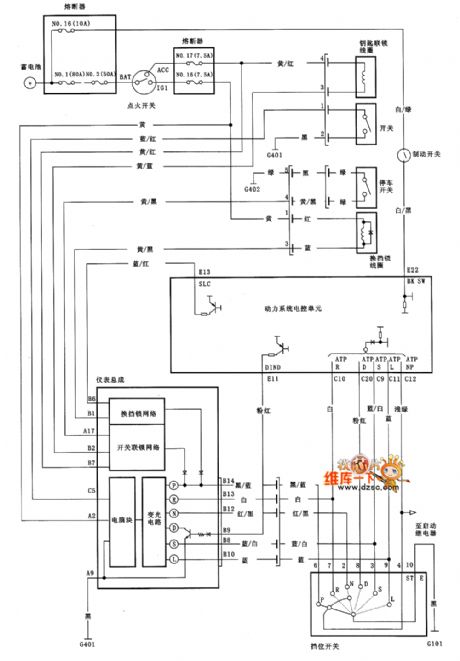
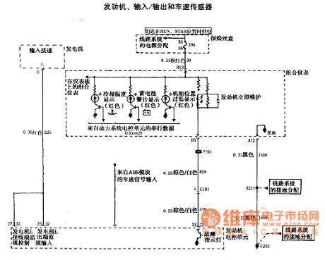
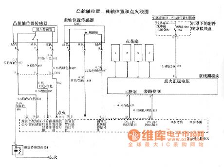
HONDA Fit starter control module and dynamical system control module circuit diagram(5)
Published:2011/5/9 4:23:00 Author:Nicole | Keyword: HONDA Fit, starter, control module, ynamical system
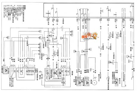
View full Circuit Diagram | Comments | Reading(1191)
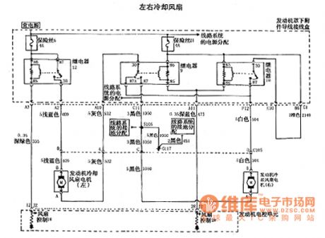
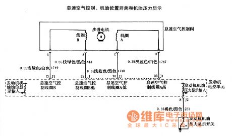
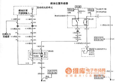
HONDA Fit 6-gear automatic transmission and 7-gear model circuit diagram
Published:2011/5/9 4:25:00 Author:Nicole | Keyword: HONDA Fit, 6-gear, automatic transmission, 7-gear, model
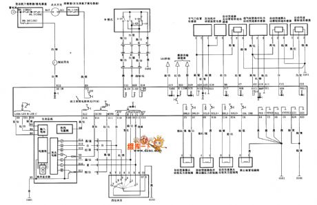
View full Circuit Diagram | Comments | Reading(875)
Jetta vanguard anticorrosion anti-lock braking system circuit diagram
Published:2011/5/9 4:30:00 Author:Nicole | Keyword: Jetta, vanguard, anticorrosion, anti-lock braking system
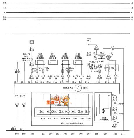
View full Circuit Diagram | Comments | Reading(545)
Passat V6 car telephone circuir diagram
Published:2011/5/9 4:17:00 Author:Nicole | Keyword: Passat V6, car telephone
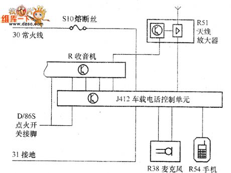
View full Circuit Diagram | Comments | Reading(478)
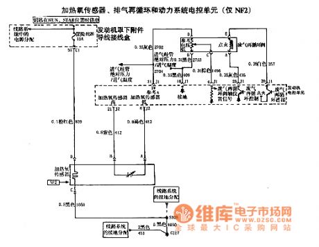
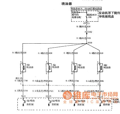
HONDA Fit automatic transmission interlock system circuit diagram
Published:2011/5/9 4:21:00 Author:Nicole | Keyword: HONDA Fit, automatic transmission, interlock system
View full Circuit Diagram | Comments | Reading(1028)
28V, 10A regulated power supply circuit diagram composed of MPC1000
Published:2011/5/9 4:24:00 Author:Ecco | Keyword: 28V, 10A , regulated power supply

View full Circuit Diagram | Comments | Reading(974)
Galanz WP750B microwave circuit diagram
Published:2011/5/9 4:15:00 Author:Ecco | Keyword: Galanz , microwave

Galanz WP750B microwave circuit diagram is shown as the chart.
(View)
View full Circuit Diagram | Comments | Reading(4022)
T feedback network circuit diagram
Published:2011/5/9 4:27:00 Author:Ecco | Keyword: T , feedback network
View full Circuit Diagram | Comments | Reading(750)
HR6184 Philips cleaner circuit diagram
Published:2011/5/9 4:06:00 Author:Ecco | Keyword: Philips , cleaner

HR6184 Philips cleaner circuit diagram is shown as the chart.
S-power switch, T-filter inductor, VS-Triac, VD-bidirectional trigger diode, L1, L2-motor stator windings, M-motor, RP1-speed potentiometer, RP2-tuning resistor. (View)
View full Circuit Diagram | Comments | Reading(622)
HR65 series of Philips cleaner circuit diagram
Published:2011/5/9 4:12:00 Author:Ecco | Keyword: Philips , cleaner

HR65 series of Philips cleaner circuit diagram is shown as the chart.
XT-terminal board, X1 ~ X6 -plug terminals, S2-motor switch, S1-power switch, M-motor, VS-Triac, VD1-bidirectional trigger diode, RP1-speed potentiometer, RP2-tuning resistor (View)
View full Circuit Diagram | Comments | Reading(687)
The 2.0L motor circuit diagram 12 of Shanghai GM Regal car
Published:2011/5/9 4:23:00 Author:Ecco | Keyword: 2.0L motor, Shanghai , GM , Regal


The 2.0L motor circuit diagram 12 of Shanghai GM Regal car is shown as the chart.
(View)
View full Circuit Diagram | Comments | Reading(477)
± 15V symmetrical regulated power supply circuit diagram composed of LC1468G
Published:2011/5/9 4:26:00 Author:Ecco | Keyword: ± 15V , symmetrical, regulated power supply

View full Circuit Diagram | Comments | Reading(1193)
RY926 ceiling fan speed governing integrated circuit diagram
Published:2011/5/9 3:31:00 Author:Ecco | Keyword: ceiling fan, speed governing, integrated circuit
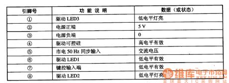

RY926 is the ceiling fan speed governing integrated circuit, which is widely used in the program control circuit of the ceiling fan and power adjusting and automatic light adjustment control of a variety of small household appliances. 1. Pin functions and data RY926 IC uses 8-pin dual in-line package, the pin functions and data are listed in Table. 2. The typical application circuit The ceiling fan speed control system typical application circuit composed of RY926 IC is shown as the chart.
(View)
View full Circuit Diagram | Comments | Reading(2488)
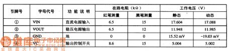
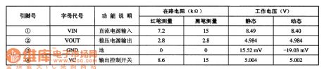
PT2398 reverberation processing integrated circuit diagram
Published:2011/5/9 3:07:00 Author:Ecco | Keyword: reverberation processing , integrated circuit

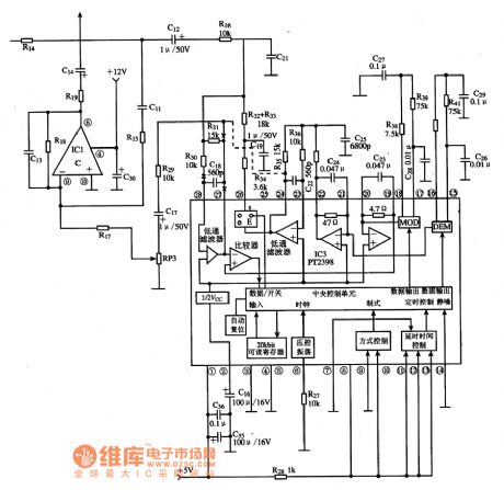
PT2398 is the reverberation processing integrated circuit produced by PT company, it is widely used in various audio systems as reverberation processing. 1. Features of functionsPT2398 IC includes low-pass filter circuit, voltage controlled oscillator circuit, delay time control circuit, mode control circuit, the central control unit circuit and its related subsidiary circuit. 2. Pin functions and data PT2398 IC uses 28-pin dual in-line package, the pin functions and data are listed in Table. 3. The typical application circuit The block diagram and the typical application circuit of PT2398 integrated circuit are shown as the chart.
(View)
View full Circuit Diagram | Comments | Reading(1989)
Four-terminal controllable voltage regulation integrated circuit diagram
Published:2011/5/9 2:37:00 Author:Ecco | Keyword: Four-terminal , controllable , voltage regulation , integrated circuit
PQ12RD11 is the 12V four-terminal controllable voltage regulator integrated circuit, which is widely used in the controlled power supply circuit of DVD players, color TVs, computer monitors, printers, fax machines and all kinds of household powers. 1. Features of functionsPQ12RD11 IC includes 12V power supply circuit, power supply circuit being ON / OFF control circuit and other ancillary functions circuit. 2. Pin functions and data PQ12RD11 IC is packaged with 4 pins in a single row , the pin functions and data are listed in Table. 3. The typical application circuit The typical application circuit of PQ12RD11 IC is shown in Figure.
(View)
View full Circuit Diagram | Comments | Reading(481)
PT2126 fan monolithic microcomputer integrated circuit diagram
Published:2011/5/9 3:38:00 Author:Ecco | Keyword: fan , monolithic, microcomputer , integrated circuit


PT2126 is the fan monolithic microcomputer integrated circuit, which is widely used in a variety of program-controlled system in fans. PT2126 IC has many pin count packages which is according to a variety of different suffixes, the corresponding relationship between pins and the pin functions are listed in Table, the typical application circuit is shown as the chart.
(View)
View full Circuit Diagram | Comments | Reading(782)
PT2124 fan monolithic microcomputer integrated circuit diagram
Published:2011/5/6 1:36:00 Author:Ecco | Keyword: fan , monolithic, microcomputer, integrated circuit


PT2124 is a fan single-chip microcomputer integrated circuit, which is widely used in fans and a variety of speed or power adjustment of small household appliances. PT2124 IC uses the package with 16-pin in double row, working voltage is 3 ~ 6V, quiescent current is 100μA, output current of SCR trigger is 7.6mA. The pin functions and data are listed in Table, the typical application circuit is shown as the chart. PT2124 IC pin functions and data The typical application circuit of PT2124 IC
(View)
View full Circuit Diagram | Comments | Reading(753)
PQ05MD21 5V four-terminal voltage regulator integrated circuit diagram
Published:2011/5/9 3:16:00 Author:Ecco | Keyword: 5V, four-terminal , voltage regulator , integrated circuit
PQ05MD21 is the 5V controlled voltage regulator four-terminal integrated circuit, which is widely used as voltage regulator circuit in DVD players, color TV, computer monitors, and a variety of household electrical power supply.1. Features of functionsPQ05MD21 IC includes 5V power supply circuit, power supply circuit on / off control circuit, and other ancillary functions circuit. 2. Pin functions and data PQ05MD21 IC is packaged with 4 feet in a single row, the pin functions and data are listed in Table. 3. The typical application circuit The power typical application circuit composed of PQ05MD21 integrated circuit is shown as Figure.
(View)
View full Circuit Diagram | Comments | Reading(547)
10-point common anode logarithmic display driver circuit diagram composed of TA7612AP
Published:2011/5/9 2:49:00 Author:Ecco | Keyword: 10-point , common anode , logarithmic , display, driver
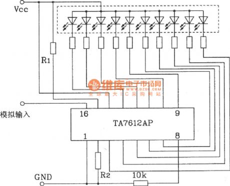
10-point common anode logarithmic display driver circuit diagram composed of TA7612AP is shown as the chart.
The input signalof thiscircuit is an analog voltage input with a logarithmic scale display.
(View)
View full Circuit Diagram | Comments | Reading(1381)
ZJ-100VA emergency improved power supply circuit diagram
Published:2011/5/9 4:15:00 Author:Rebekka | Keyword: emergency improved power supply
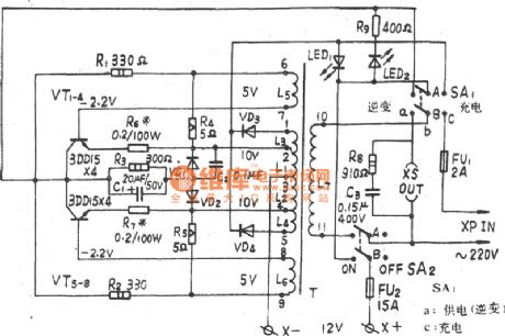
ZJ-100VA emergency improved power supply circuit diagram. (View)
View full Circuit Diagram | Comments | Reading(572)
| Pages:1927/2234 At 2019211922192319241925192619271928192919301931193219331934193519361937193819391940Under 20 |
Circuit Categories
power supply circuit
Amplifier Circuit
Basic Circuit
LED and Light Circuit
Sensor Circuit
Signal Processing
Electrical Equipment Circuit
Control Circuit
Remote Control Circuit
A/D-D/A Converter Circuit
Audio Circuit
Measuring and Test Circuit
Communication Circuit
Computer-Related Circuit
555 Circuit
Automotive Circuit
Repairing Circuit