Remote Control Circuit
A Protection Circuit of Default Phases of Three-Phase Three-Wire Power Sources
Published:2011/5/7 19:48:00 Author:Borg | Keyword: Default Phases, Three-Phase, Three-Wire, Power Sources | From:SeekIC
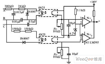
The following is a circuit used toprotect the defult-phases of three-phase three-wire power sources. Without anyone of A,B or C, the electrical level (LEV) that the optical coupler output will be lower than the reference voltage that the inverting input node of the comparator holds, and the latter will low LEV to block the PWN driving signals, finally, the supply power will be shut down. Besides, if the input polar of the comparator changes, the PWM signals can also be blocked by high LEV. This circuit separates heavy currents by optocouplers, which is safe to use, while RP1 and RP2 are used to adjust the threshold values of the protecting behaviors.
Reprinted Url Of This Article:
http://www.seekic.com/circuit_diagram/Remote_Control_Circuit/A_Protection_Circuit_of_Default_Phases_of_Three_Phase_Three_Wire_Power_Sources.html
Print this Page | Comments | Reading(3)

Article Categories
power supply circuit
Amplifier Circuit
Basic Circuit
LED and Light Circuit
Sensor Circuit
Signal Processing
Electrical Equipment Circuit
Control Circuit
Remote Control Circuit
A/D-D/A Converter Circuit
Audio Circuit
Measuring and Test Circuit
Communication Circuit
Computer-Related Circuit
555 Circuit
Automotive Circuit
Repairing Circuit
Code: