Basic Circuit
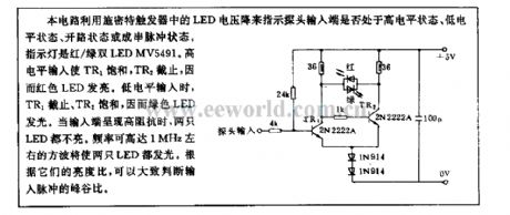
TTL state probe circuit
Published:2011/5/8 21:21:00 Author:Nicole | Keyword: TTL state probe | From:SeekIC

This circuit uses LED voltage drop of Schmitt trigger to indicate whether the probe input terminal is in high level state, low level state, open circuit state or string pulse state. The indicator light is red/green double LED MV5491. When it is high level input, TR1 is saturation, TR2 turns off, so red LED lights. When it is low level input, TR1 turns off, TR2 is saturation, so green LED lights. When the input terminal is high impedance, the two LEDs are all off. The square wave with 1MHz maximum frequency can make two LEDs light. According to their brightness ratio, it can judge the peak-to-trough ratio of input pulse.
Reprinted Url Of This Article:
http://www.seekic.com/circuit_diagram/Basic_Circuit/TTL_state_probe_circuit.html
Print this Page | Comments | Reading(3)

Article Categories
power supply circuit
Amplifier Circuit
Basic Circuit
LED and Light Circuit
Sensor Circuit
Signal Processing
Electrical Equipment Circuit
Control Circuit
Remote Control Circuit
A/D-D/A Converter Circuit
Audio Circuit
Measuring and Test Circuit
Communication Circuit
Computer-Related Circuit
555 Circuit
Automotive Circuit
Repairing Circuit
Code: