
Circuit Diagram
Index 123
LIGHT BULB TIMER
Published:2013/5/7 21:26:00 Author:muriel | Keyword: LIGHT BULB TIMER
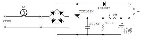
Occasionally you might have a need to keep a light on for a certain time, usually a few minutes, and be sure that it switches off even if you forget to turn off the switch. This could be useful in a cellar or in a closet. The circuit will switch on a light bulb simply by pressing the push button. After a time of 3-7 minutes it will switch off automatically. The long delay is achieved by partly using the leakage current between anode and gate of the scr. This current is dependent almost on anything: voltage, temperature, lamp power, scr device, etc., this is the reason why the timing is not constant but for the intended application it is not important. If the delay is too short you may increase the 220nF capacitor up to 470nF. Too high a value will keep the light always on. It will work with incandescent light bulbs only. Its operation with electronic lamps is erratic and the delay is only 1 or 2 minutes. The scr must be the sensitive gate type and no other type was tested except the TIC106N.
The circuit is rather small and could be housed in the same case as the push button, if there is enough room. Of course you have to substitute the standard switch with a push button. Operation with a 110Vac mains has not been tested although I expect that a 100μF 100V capacitor instead of the 47μF capacitor should do the trick.
It goes without saying that you must know what you are doing as working with the household mains can be dangerous and remember to switch off the mains breaker before doing any work on the electric wiring. Do not attempt to install this circuit if you have doubts on its operation, connections and relevant safety measures. (View)
View full Circuit Diagram | Comments | Reading(1039)
DOMESTIC POWER LIMIT WARNING
Published:2013/5/7 21:26:00 Author:muriel | Keyword: DOMESTIC POWER LIMIT WARNING
Since a new electricity meter, the electronic variety, was installed at my place, I get cut off if I exceed the set power level, 3.3KWh in my case.
The new meter is unforgiving and although there is a little tolerance built in, you really never know when it has gone over the cut off limit, given the number of electric appliances which are continuously switched on and off.
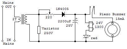
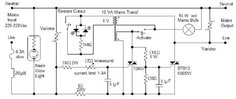
The circuit was designed to give an audible warning when the 3.3KWh limit is exceeded. The transformer is a disused transformer from a soldering gun. It is relatively easy to remove the few turns of the secondary winding and rewind two turns of thick wire, as thick as the wire coming from the meter at least. One turn should be enough if you have a limit of 6.6KWh, but operation at this power level was not tested. As an alternative you may try a small toroidal mains transformer: it is easy to add a few turns of thick wire. Ignore all other windings, if any, except the primary winding, which in our circuit becomes the secondary winding. The circuit is to be installed between the electricity meter with its breaker and the house wiring. With the given components, the circuit will oscillate at 1 sec. on and 1 sec. off, depending on the load. Adjust the potentiometer so that there is no sound below the power limit. The varistor is necessary in case there is a short in the house wiring: the extra voltage at the secondary may damage the circuit. The piezo buzzer can even be placed away from the circuit in any place where it can be easily heard.
It goes without saying that you must know what you are doing as working with the household mains can be dangerous and remember to switch off the mains breaker before doing any work on the electric wiring. Do not attempt to install this circuit if you have doubts on its operation, connections and relevant safety measures. (View)
View full Circuit Diagram | Comments | Reading(1173)
SIMPLE WARNING SIGNAL
Published:2013/5/7 21:25:00 Author:muriel | Keyword: SIMPLE WARNING SIGNAL

This power audio oscillator could be used as a warning signal for alarm systems or to attract attention if something is wrong with an equipment. The oscillator, about 750Hz, exploits the characteristic of certain NPN transistors, in this case a BC337, to oscillate if reverse biased and with the base open. Other equivalent transistors might not work. Despite its simplicity the circuit is quite flexible: the 390Ω resistor, normally connected to negative could be switched in through a logic circuit, so it can be driven directly by the circuit to be monitored; the base is normally not used but frequency modulation of the circuit is possible by connecting a modulating signal to the base via a high value resistor, typically 2.2MΩ.
A 3W loudspeaker is adequate for the circuit and it can be either an 8 or 4Ω loudspeaker, although in the latter case a small heatsink is necessary for the BD436. Peak current for an 8Ω loudspeaker can be as high as 1.2A but because the duty cycle is relatively small, the average current was measured at 0.2A hence the overall power requirement is only 2.4W despite the high volume the circuit is capable of. The feed line must be well filtered and can be anything between 9 and 15V although adjustment of the resistor might be required as the oscillation frequency is sensitive to the supply voltage. (View)
View full Circuit Diagram | Comments | Reading(698)
10A CAR BATTERY CHARGER
Published:2013/5/7 21:25:00 Author:muriel | Keyword: 10A , CAR BATTERY CHARGER

The charger is suitable for lead-acid car batteries and it is assembled in two units: a metal box with the toroidal transformer, instrument, lights, etc, and a small plastic box housing the voltage and temperature circuit. Connection between main box and sensor is realized with a standard 3 core x 1mm, electric cable, 4m long. Its resistance is factored in the circuit calculations and it is the limiting resistor against overcurrent. Do not change type or length as it may alter the overall performance and safety of the charger. The sensor box is typically positioned close to the battery to be charged and two short flexible leads, 2mm section, 30cm long, one red and black the other, terminated with good quality clamps make up the connection from the sensor to the battery.
This solution assures that the battery is charged up to the correct voltage which depends, in turn, upon the ambient temperature. The final voltage should be set, with the 200Ω multiturn pot, at 14.8V at 20°C-68°F and derated +/-30mV/°C (17mV/°F) at any other temperature. For example, if the prevailing ambient temperature is 10°C then the final voltage should be set at 15.1V, if the prevailing ambient temperature is 30°C the final voltage is 14.5V and so on. Once set, the circuit will automatically adjust the voltage to within 1°C. You have to connect a battery in order to carry out this setting.
A thermistor would have simplified the circuit but its correct implementation is not easy and it was preferred to employ a number of diodes. A red led in the sensor box gives an indication of the correct connection to the battery. However the circuit is quite tolerant to mistakes: shorting the output will do no arm as there is no voltage at the output terminals, not until you connect it to the battery. It is the battery voltage that triggers the circuit into operation and once it is disconnected from the battery the voltage too disappears from the output. Only if the battery voltage is above 7-8V then the circuit will operate. A reverse connection of any battery will do no arm either as the circuit will simply not operate. It will withstand a temporary connection of a 24V battery; above this voltage the input circuit is overloaded and could be damaged.
Current control is achieved by switching the SCRs at the appropriate time through the BF761 collector current. The blue led, but any other colour will do, gives an indication that the unit is charging the battery. The led will start flickering at the end of the charging cycle so you know at a glance that the charge is coming to an end. You may leave the battery connected after it has fully charged as there will be a trickle charge which will keep the voltage at its optimum level. Switching noise is eliminated by the 85μH choke made up by winding 27 turns of 1mm enamelled wire on a ferrite ring 27x11mm. Due to the way SCRs operate, the common line is positive and not negative as one would expect. Care must be exercised when connecting all the polarity sensitive devices.
A toroidal transformer has many advantages: it is small, highly efficient, will tolerate a moderate overload and will consume little power, only 3.5VA when switched on and no battery connected. Cost, at this power range, is surprisingly close to a traditional transformer, yet, the inrush current when switched on can be so high, depending on the exact time with respect to the mains sinewave, that the collapse of the ensuing strong magnetic field will produce mighty spikes up to 500V at the secondary, destroying whatever they find in their path. A few capacitors, the use of fast diodes UF4006 and the high voltage transistor BF761 take care of the problem. The main switch should be rated at 10A.
SCRs can get rather hot; the best solution is to mount them on the metal case itself using appropriate insulating kits. As a consequence the box will warm up especially at the beginning of the charging cycle when the unit may be temporarily overloaded. A thermal switch is provided to cut out the mains supply under extreme temperature and overload conditions. This switch is mounted at about 6-8cm away from the SCRs so that it will take care of the heat coming from other sources as well, such as the transformer and the choke.
The unit has been tested with batteries from 44 to 100Ah for over a year, from 0 to 38°C (32 to 100°F); the upper temperature limit caused the thermal switch to operate. I should relocate the thermal switch in a cooler place if the designed max operating temperature of 40°C-104°F is to be met. You may have different temperature limits depending on the mechanical configuration of the box and internal components layout. Pay attention to the fact that this charger behaves like a fast charger for the smaller batteries and precautions should be taken concerning gas production and it is good practice to disconnect the battery from the car before charging it. (View)
View full Circuit Diagram | Comments | Reading(3438)
POINT-CONTACT OSCILLATORS
Published:2013/5/7 21:24:00 Author:muriel | Keyword: POINT-CONTACT OSCILLATORS
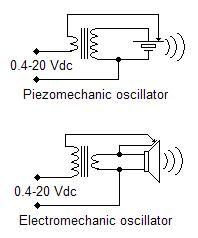
The principle of operation of a car hooter has been applied to both a ceramic sounder and a loudspeaker. A break in the supply current is caused by the vibration of the ceramic sounder plate or the speaker membrane. You could implement similar circuits even without a transformer but the voltage range will be limited, there will be too much sparking at the contact point and pressure and position of the contact become critical. The transformer introduces a feedback mechanism thus eliminating or drastically reducing all mentioned negative effects. An output transformer is used in both circuits: one of the winding is normally 4 or 8Ω while the other is at a higher impedance. The larger plate of the piezomechanic oscillator goes to positive through the contact, typically an adjustable screw, and the transformer low impedance winding. To get the correct phase relationship you may need to reverse one of the windings. A similar transformer is used for the electromechanic oscillator with the low impedance winding connected to the speaker. Also in this case you may need to reverse one of the windings but first you must make sure that the speaker cone goes forward when the voltage is applied: reverse the speaker connections if necessary. A small copper strip is glued on the back of the speaker membrane with a screw placed in the speaker casing so that it just touches the copper strip.
Frequency of operation is from 1 to 1.5 KHz for both oscillators. The frequency for the electromechanic oscillator depends mainly on the speaker damping factor: best results are obtained with the speaker laid against a flat surface or sealing the front side with a wooden panel. Operation below 0.4-0.6V depends on the careful adjustment of the screw and mechanical precision of the assembly. (View)
View full Circuit Diagram | Comments | Reading(817)
PIEZOELECTRIC TRANSFORMER
Published:2013/5/7 21:23:00 Author:muriel | Keyword: PIEZOELECTRIC TRANSFORMER
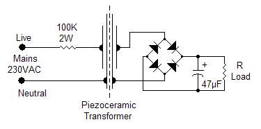
If there is a need to feed very low power devices you may resort to infrared optocouplers, solar cells, batteries or low power transformers although the latter might be rather oversized for the intended purpose. Eventually, with the exception of solar cells, all of them draw power from the mains so it might be convenient to use a piezoelectric transformer if the power required is in the range 0.1 to 0.3 mW. The schematic shows an easy implementation of such a transformer. Two piezoceramic sounders are glued back-to-back so that the mechanical movement of the first, the primary, is transferred to the second, the secondary. The ac output voltage can be used as it is or rectified in order to feed micropower electronic equipment or trickle charge small backup batteries. The actual implementation requires two ceramic sounders with high intrinsic capacitance: sounders with 80 to 110nF are readily available and usually come as 50mm discs. Two of these discs are cut down to 35mm in order to have a more compact unit and a lower stray capacitance between primary and secondary. A layer of double-sided adhesive tape is laid on the larger plate of each sounder in order to assure proper electrical insulation between primary and secondary. The sides of the sounders are then pressed against each other and the transformer is ready to operate.
R Load
VAC
VDC
100 KΩ
5.1
4.67
47 KΩ
4.22
3.29
22 KΩ
2.77
2.06
10 KΩ
1.41
1.1
4.7 KΩ
0.68
0.56
The table shows the measured output under several loading conditions: the ac output was measured with the load directly across the output terminals while the dc output was measured with a full wave rectifier in place. The measured dc voltage refers to a schottky bridge rectifier but the use of standard 1N4004 diodes will only show a modest 6-8% voltage decrease. Measurements were taken with the transformer operating in free air, without any holder, but a proper mechanical layout would require the transformer to be firmly held by the edge of the disc. The use of a plastic box is mandatory for safety reason and improves the transfer of mechanical energy to the secondary thus obtaining a 15-20% voltage increase. (View)
View full Circuit Diagram | Comments | Reading(1302)
ELECTRONIC FUSE 3
Published:2013/5/7 21:22:00 Author:muriel | Keyword: ELECTRONIC FUSE
View full Circuit Diagram | Comments | Reading(584)
CAR BATTERY TESTER
Published:2013/5/7 21:22:00 Author:muriel | Keyword: CAR BATTERY TESTER

Checking the status of your car battery (accumulator) should be easier with this circuit which measures the internal resistance of the battery. Pulses generated by the 555 are used to drive a dummy load and the AC voltage which develops across the battery gives an indication of its internal resistance: the lower the voltage the healthier the battery. The AC voltage is read out by means of a digital meter connected at the output. Separate leads are used for the dummy load and for the metering circuit. They should be connected to their respective battery lugs but they should not touch each other. This avoids erroneous readings due to less than perfect contacts of the dummy load. The internal resistance depends on the battery temperature as well; this is the reason for the switch: hot means a battery (not ambient) temperature between 35 and 52 degrees Centigrade, normal is for a temperature between 16 and 34 degrees and cold is good for a temperature from -4 to 15. Beyond these ranges the reading is unreliable. The internal resistance depends also on the rated capacity of the battery. The 100 ohm potentiometer sets the battery capacity: it is rotated totally to positive for a 100Ah battery and totally to negative for a 32Ah battery. A dial with uniform markings from 32 to 100 was used in the prototype. This means we can measure internal resistance of batteries rated from 32 to 100Ah. As there are a number of smaller 12V batteries around, specially for alarm systems, a switch was introduced that, in the X1 position, will change the capacity range to 3.2 - 10Ah. The unit has six leads going out of the box: two for the dummy load, two for the metering section and two going to the digital meter. Operation is simple: set the range, temperature and battery rating, then connect the dummy load and the metering leads to the battery lugs and read the ac voltage: you should be safe if it reads below 10-12mV otherwise it is better to give the battery a good recharge and if it is still beyond 10-12mV then probably you need a new battery. A bright orange LED shows that the unit is connected and in operation. (View)
View full Circuit Diagram | Comments | Reading(3783)
5W INVERTER
Published:2013/5/7 21:21:00 Author:muriel | Keyword: 5W INVERTER
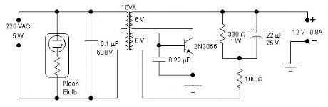
A single transistor is all you need for this simple inverter. The main aim of this circuit is to provide a suitable supply for all kind of low power battery chargers that normally connect to the mains such as mobile phones, electric shavers, etc, even an electronic neon light rated at 5W was successfully connected. Only easily obtainable components are used. The transformer is a standard 10VA mains transformer with two 6V windings connected as shown in the schematic. Frequency of operation is between 70 and 190Hz depending on the nature of the load. This frequency is acceptable by most devices but obviously it is not suitable to drive frequency dependent appliances such as clocks or small motors that depend on the mains frequency in order to operate reliably. The transistor will not require any additional heatsink if it is assembled on the metallic case provided for the inverter. The neon glow light will give a useful indication, and warning, on the presence of a dangerous voltage at the output. A 2.5A fuse on the input supply line would be a useful addition. Operation is simple: switch on the unit and connect the load keeping an eye on the neon glow light which should be always on: certain switching chargers demand an initial peak current effectively shorting the output and switching off the neon: in this case you have to try repeatedly to connect the load until it works. A temporary short at the output and a temporary voltage reversal at the input will not damage the unit. Efficiency was not a design parameter however it was measured to be between 50 and 60%. If you have a 110V mains transformer and consequently a 110VAC output you should change the 0.1μF capacitor to 0.22μF, 400V. The waveform is only vaguely sinusoidal. Invert the connection of one of the 6V windings if oscillations do not set in. (View)
View full Circuit Diagram | Comments | Reading(709)
ALKALINE CHARGER
Published:2013/5/7 21:20:00 Author:muriel | Keyword: ALKALINE CHARGER
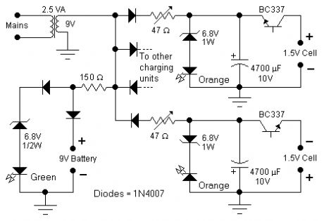
This circuit was specifically designed to recharge alkaline cells. The unusual connection of the transistor in each charging unit will cause it to oscillate, on and off, thus transferring the charge accumulated in the capacitor to the cell. The orange LED will blink for around 5 times a second for a 1.37V cell. For a totally discharged cell the blinking is faster but it will decrease until it will come to a stop when the cell is charged. You may leave the cell in the charger as it will trickle charge and keep it at around 1.6V. To set the correct voltage you have to connect a fresh, unused cell and adjust the trimmer until oscillations set in, then go back a little until no oscillation is present and the circuit is ready to operate. You should use only the specified transistors, LED colors, zener voltage and power rating because they will set the final voltage across the cell. A simple 9V charging circuit was also included: it will charge up to around 9.3V and then keep it on a trickle charge: the green LED will be off while charging and will be fully on when the battery is close to its final voltage.
A 2.5VA transformer will easily charge up to 4 cells at the same time although 2 only are shown in the schematic. In order to minimize interference from one circuit to the other they have nothing in common except the transformer and, in order to show a balanced load to the transformer, half of the charging units will use the positive sinewave and the other half the negative sinewave. Make sure to use high beta transistors such as BC337-25 or better BC337-40. Given the dispersion of the transistor parameters it might happen that oscillations do not take place. Use a slightly higher zener voltage: 7.5V instead of 6.8 or a green led in place of the orange ones.
All types of alkaline cells can be recharged: it will take 1 day for a discharged AA cell or 9V battery and up to several days for a large D type cell. The best practice is not to discharge completely the cell or battery but rather to give a short charge every so often although admittedly this is not easy to achieve. Do not attempt to recharge a totally discharged cell or a cell showing even the slightest sign of damage.
I tried successfully to recharge NiMH cells as well. Although the charging profile for these cells is quite different from alkaline cells, the circuit seems to work fine provided you do not leave them in the charger forever, because of the possibility of overcharging especially for the smaller batteries.
The mains transformer must be suited for the voltage available in each country: usually 230Vac or 115Vac. (View)
View full Circuit Diagram | Comments | Reading(1128)
MINIMAL AUDIO OSCILLATORS
Published:2013/5/7 21:20:00 Author:muriel | Keyword: MINIMAL AUDIO OSCILLATORS
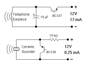
In order to generate a single note you may try these simple circuits. With only three components you may implement some basic buzzers. You need a telephone earpiece for the first circuit. Any old telephone set has got one of those magnetic earpiece that is right for our purposes. Add an extra capacitor and a transistor and you have your buzzer. Frequency of operation is about 1800 Hz and the capacitor must be changed if you wish to have a different frequency. The second circuit is implemented with a ceramic sounder: its intrinsic capacity is used to make another simple buzzer. Working frequency is 800 Hz and power drain is really low. The operating voltage is 9,5 - 20V for the circuit with the ceramic sounder and 8 - 16V for the other circuit. Do not expect a loud sound level: it is rather limited just as the current drain is. These buzzers are suitable for audio signaling on portable devices and wherever it is necessary to have a sound source implemented with a minimum components count. Not all transistors will oscillate: you have to use the specified type although I found that the BC109 and 2N2222A will also work albeit at a slightly different voltage. (View)
View full Circuit Diagram | Comments | Reading(648)
ELECTRONIC RELAY
Published:2013/5/7 21:19:00 Author:muriel | Keyword: ELECTRONIC RELAY
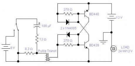
In some applications where you require speed of operation and no contact bouncing, you may find this circuit helpful. This is really the implementation of an SCR with discrete components. The medium power complementary pair will switch on and off a load up to 3A. You may modify the circuit to carry up to 10A using suitable power transistors and diodes. The left side of the circuit shows a typical drive. This electronic relay will latch in the on or off position depending on the direction of the pulse going through the primary winding of the transformer. You may omit the capacitor altogether; in this case the circuit behaves very much like the coil of a relay: when you apply a voltage to the primary it will switch on and when you remove the voltage it will switch off. The drawback in this second case is that there is a large amount of power dissipated in the 12Ω resistor which must be rated accordingly. The pulse transformer is recovered from a faulty electronic neon light. The drive circuit for these lamps always includes a pulse transformer. The higher impedance, or resistance, is the primary and the other winding is the secondary. The measured resistance was below 0.4Ω and the inductance was 680 and 47μH for the primary and secondary respectively. The ideal would be a pulse transformer with two secondary windings so that both transistors could be driven but you have the same results if the drive is applied to one transistor only. The circuit has its limitations: there is a voltage drop across the switch, in the on state, between 0.7 and 1V, this may not be acceptable in low voltage applications; it will work only with DC supplies and there is a minimum sustain current, 12mA in the circuit shown. Below this current the switch will revert to its off state. You may, of course, design a circuit with low power transistors with a sustain current of only a few μA if necessary. (View)
View full Circuit Diagram | Comments | Reading(650)
MAINS FREQUENCY METER 2
Published:2013/5/7 21:19:00 Author:muriel | Keyword: MAINS FREQUENCY METER
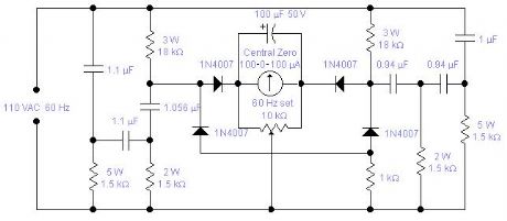
WARNING! This circuit is directly connected to the mains and should be assembled in a box which will avoid access to any of its part and care must be exercised when calibrating the unit. If you live in the States or you have a 110 VAC, 60 Hz mains, you may try the second circuit: the reported values are calculated values, I did not actually test the unit. The odd capacitors values are easily obtained with the combination of standard values: 0.94 is 2 x 0.47 in parallel, 1.056 is 1μF + 56nF in parallel and 1.1 is 1 + 0.1μF.
(View)
View full Circuit Diagram | Comments | Reading(1282)
MAINS FREQUENCY METER 1
Published:2013/5/7 21:18:00 Author:muriel | Keyword: MAINS FREQUENCY METER
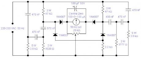
Mains frequency is pretty stable and it is unlikely that you have to measure it but if you have an emergency generator you might find this circuit useful as it will give an indication whether the generator is running too fast or too slow. Actually you can use the mains frequency to calibrate it by adjusting the 25K multiturn trimmer until it reads 0. The odd looking components values are easily obtained using standard values: 3777 is 3900 in parallel with 120KΩ, 4020 is 3900 and 120 in series, 570nF is 470nF with 100nF in parallel and 400nF is 4 x 100nF capacitors in parallel. Components should be chosen for their stability and precision. 1% tolerance would be ideal but 5% is acceptable so long as you measure them with a good meter. Capacitors should be properly rated for direct connection to the mains and resistors should have a low temperature coefficient as it will adversely affect the zero setting and change the filters response. The 100μF capacitor could be occasionally reverse biased with a voltage of 0.1-0.2 V. There is no problem for the capacitor which is generously rated. Operation is quite simple: connect it first to the mains, wait about 4-5 minutes until all resistors reach their working temperature, calibrate, and then connect to the generator. (View)
View full Circuit Diagram | Comments | Reading(1655)
LONG DELAY TIMER 2
Published:2013/5/7 21:16:00 Author:muriel | Keyword: LONG DELAY TIMER
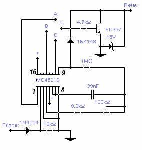
A max. delay of 20 hours is achieved by this relatively simple circuit. A permanent ground, or no signal, at the trigger input starts the timer. A ground at the relay output is available after a set time that depends on the connection of the transistor base (X) to one of the counter output: connection with (C) gives a min. delay of 1m 40s and max. of 18m 30s. Connection with (B) gives a min. delay of 13m 20s and max. of 2h 28m. Connection with (A) gives a min. delay of 1h 47m and max. of 20h. Supply voltage is between 6 and 15V and longer delay could be obtained by increasing the capacitor value up to 10 times with a delay in excess of 1 week. A positive at the trigger input will reset the counter. Adjust the 100K pot. for the desired timing. The load is typically a relay but any load with a max. current of 200 mA will work fine. Admittedly this is not a very original circuit but can save some time if you need to build one. The IC is a Cmos 24-stage binary counter MC4521B from Fairchild, or alternatively, you may use the MC14521B from Motorola. (View)
View full Circuit Diagram | Comments | Reading(1163)
SINGLE LED FLASHER
Published:2013/5/7 21:16:00 Author:muriel | Keyword: SINGLE LED FLASHER

Flashing a LED should not require a complex circuit. A reverse biased transistor does the job in a nice way. Circuit a flashes the LED twice a second: changing the capacitor and/or the resistor will change the frequency, also the supply voltage will influence its frequency of operation. A BC337 can be used instead of the 2N2222A; in this case the supply voltage can be lowered to 9V. Circuit b gives the same result but it will work directly off the mains, so be careful with the live wire because it can be a hazard if you do not take all necessary precautions. If the mains voltage is 110VAC the resistor should be decreased from 100K to 47K. If a BC337 is used, then the resistor is 390K for a 220V mains and 180K for a 110V mains. The zener is not required for its operation: it is only a safety measure that avoids voltage build up if the LED gets disconnected. When you reconnect it, the current surge will destroy the transistor and the LED. The capacitor could be damaged as well. (View)
View full Circuit Diagram | Comments | Reading(0)
BASIC INFRARED TX-RX
Published:2013/5/7 21:14:00 Author:muriel | Keyword: BASIC INFRARED TX-RX

The transmitting section of this infrared tx-rx is unusually simple but it works rather well: the infrared LED pulses at a frequency of 160Hz and its range, with its receiver, is between 2 and 4m depending on the transformer used and the setting of the 100k pot. With other receivers it may reach a range of 15m, without any lens but with a perfect alignment between tx and rx. The receiving section uses an infrared phototransistor and an additional infrared emitter is placed next to it in order to provide a light bias thus improving sensitivity. The 100k pot. will also adjust sensitivity by setting the right operating point for the transistor. The supply should be well regulated in order to avoid self-oscillations. The audio transformer is a small output transformer recovered from an old transistor radio. (View)
View full Circuit Diagram | Comments | Reading(1477)
SENSITIVE GEOMAGNETIC DETECTOR
Published:2013/5/7 21:14:00 Author:muriel | Keyword: SENSITIVE GEOMAGNETIC DETECTOR

This is a rather sensitive circuit which will detect minute variations of a magnetic field, particularly the Earth magnetic field. The principle is based on an audio beat tone generated by two identical oscillators. These must be built in the same manner with the same type of components. In this way we minimize influence from temperature and voltage variations. The two oscillators, called probes, are housed in plastic boxes padded, on the inside, with copper wires terminated in one point only and running parallel to the ferrite rod. This rod, together with the coil was removed from an old Medium Wave radio and a small and powerful magnet was glued on one side. An extra magnet was placed on the outside of one of the boxes in order to set the initial or zero beat tone. This magnet is rotated or moved up and down until you hear the right frequency. A small hole is made in each plastic box in order to adjust the trimmer capacitor. Switch S1 will enable the sub-Hertz detector: in this way you will be able to hear the beat note even if the difference between the two probes is below the threshold level of around 20Hz and you will pick up differences well below 1Hz. The two probes are connected to the main box using standard RG58 coaxial cable tested up to a length of 15m. Operating frequency is 1.25MHz and it is sensitive enough to feel the rotation of a speaker magnet 2m away. Battery voltage is 9V. (View)
View full Circuit Diagram | Comments | Reading(1957)
HIGH VOLTAGE GENERATOR
Published:2013/5/7 21:13:00 Author:muriel | Keyword: HIGH VOLTAGE GENERATOR

Easy to build, this high voltage generator is capable of generating up to 50KV but the breakdown voltage of the coil limits the voltage to a value somewhat lower. T2 is the ignition coil of a car and also the 0.5µF capacitor comes from the same place: actually I suggest using only this type of capacitor. T1 is a small transformer with a laminated iron rod, with a square section of 7x7mm, 57mm long with 75 turns on the collector side and 25 turns on the base side made with a 1mm enamelled wire. Its implementation is not critical and I expect that the circuit will work with a wide variety of transformers including ferrite ones. Try to invert one of the windings if the circuit does not oscillate. The transistor will stay quite cool and does not require a radiator if it is assembled on a metal case; otherwise a small 5ºC/W radiator will suffice. Frequency of operation is around 1.2KHz. (View)
View full Circuit Diagram | Comments | Reading(0)
ZERO CROSSING AC SWITCH OSCILLATOR
Published:2013/5/7 21:13:00 Author:muriel | Keyword: ZERO CROSSING AC SWITCH OSCILLATOR
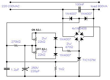
The circuit shown will switch on and off a resistive or inductive load up to 800VA with the possibility to adjust both the on and off period. Switching takes place during the zero crossing of the sine wave. The switch on point is around the zero crossing but pinpoint accuracy is not guaranteed due to the analogue nature of the circuit. The on period is adjustable between 0.3 to 4sec while the off period is adjustable between 0.2 and 10sec. The chosen SCR has a sensitive gate: this avoids the use of a large electrolytic capacitor. Frequency of operation is fairly stable although it is slightly affected by temperature, supply voltage and loading conditions. (View)
View full Circuit Diagram | Comments | Reading(759)
| Pages:123/2234 At 20121122123124125126127128129130131132133134135136137138139140Under 20 |
Circuit Categories
power supply circuit
Amplifier Circuit
Basic Circuit
LED and Light Circuit
Sensor Circuit
Signal Processing
Electrical Equipment Circuit
Control Circuit
Remote Control Circuit
A/D-D/A Converter Circuit
Audio Circuit
Measuring and Test Circuit
Communication Circuit
Computer-Related Circuit
555 Circuit
Automotive Circuit
Repairing Circuit