Basic Circuit
ELECTRONIC RELAY
Published:2013/5/7 21:19:00 Author:muriel | Keyword: ELECTRONIC RELAY | From:SeekIC

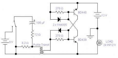
In some applications where you require speed of operation and no contact bouncing, you may find this circuit helpful. This is really the implementation of an SCR with discrete components. The medium power complementary pair will switch on and off a load up to 3A. You may modify the circuit to carry up to 10A using suitable power transistors and diodes. The left side of the circuit shows a typical drive. This electronic relay will latch in the on or off position depending on the direction of the pulse going through the primary winding of the transformer. You may omit the capacitor altogether; in this case the circuit behaves very much like the coil of a relay: when you apply a voltage to the primary it will switch on and when you remove the voltage it will switch off. The drawback in this second case is that there is a large amount of power dissipated in the 12Ω resistor which must be rated accordingly. The pulse transformer is recovered from a faulty electronic neon light. The drive circuit for these lamps always includes a pulse transformer. The higher impedance, or resistance, is the primary and the other winding is the secondary. The measured resistance was below 0.4Ω and the inductance was 680 and 47μH for the primary and secondary respectively. The ideal would be a pulse transformer with two secondary windings so that both transistors could be driven but you have the same results if the drive is applied to one transistor only. The circuit has its limitations: there is a voltage drop across the switch, in the on state, between 0.7 and 1V, this may not be acceptable in low voltage applications; it will work only with DC supplies and there is a minimum sustain current, 12mA in the circuit shown. Below this current the switch will revert to its off state. You may, of course, design a circuit with low power transistors with a sustain current of only a few μA if necessary.
Reprinted Url Of This Article:
http://www.seekic.com/circuit_diagram/Basic_Circuit/ELECTRONIC_RELAY.html
Print this Page | Comments | Reading(3)

Article Categories
power supply circuit
Amplifier Circuit
Basic Circuit
LED and Light Circuit
Sensor Circuit
Signal Processing
Electrical Equipment Circuit
Control Circuit
Remote Control Circuit
A/D-D/A Converter Circuit
Audio Circuit
Measuring and Test Circuit
Communication Circuit
Computer-Related Circuit
555 Circuit
Automotive Circuit
Repairing Circuit
Code: