
Circuit Diagram
Index 138
Curiously Low Noise Amplifier
Published:2013/3/25 3:22:00 Author:Ecco | Keyword: Low Noise Amplifier
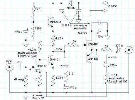
The Curiously Low Noise Amplifier takes advantage of the wonderful noise characteristics of the 2SK170 JFET that boasts a noise voltage below 1 nV/root-Hz and virtually no noise current. The noise voltage of the amplifier is only 1.4 nV/root-Hz at 1 kHz, increasing to only 2.7 nV/root-Hz at 10 Hz. The noise current is difficult to measure, so this simple utility amplifier can see the noise from a 50 ohm resistor and a 100k resistor, too. (The 1.4 nV input-referred noise will increase to about 1.7 nV with a 50 ohm resistor, instead of a short, and a 100k resistor will give an input-referred noise near 40 nV, with very little contribution from the amplifier.)
This amplifier is a utility amplifier with a gain of 100, that would typically be used in a lab setting to boost tiny signals for measurement or further processing. It isn't intended to drive a speaker or headphones directly. (It could drive the LM386 quite nicely.) The circuit is a simple discrete transistor feedback circuit with two gain stages and a unique class-A output buffer:
(View)
View full Circuit Diagram | Comments | Reading(1779)
Simple LM386 Audio Amplifier
Published:2013/3/25 3:21:00 Author:Ecco | Keyword: Audio Amplifier
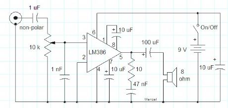
This simple amplifier shows the LM386 in a high-gain configuration (A = 200). For a maximum gain of only 20, leave out the 10 uF connected from pin 1 to pin 8. Maximum gains between 20 and 200 may be realized by adding a selected resistor in series with the same 10 uF capacitor. The 10k potentiometer will give the amplifier a variable gain from zero up to the maximum.
(View)
View full Circuit Diagram | Comments | Reading(2074)
Inversed monostable circuit
Published:2013/3/25 2:39:00 Author:Ecco | Keyword: Inversed monostable
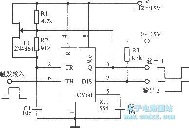
Inversed monostable circuit is shown as figure.
(View)
View full Circuit Diagram | Comments | Reading(569)
The multivibrator composed of FXl39
Published:2013/3/25 2:31:00 Author:Ecco | Keyword: multivibrator
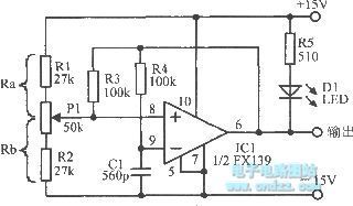
The multivibrator composed of FXl39 is shown as figure.
(View)
View full Circuit Diagram | Comments | Reading(835)
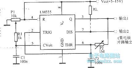
50% duty cycle oscillator
Published:2013/3/25 2:19:00 Author:Ecco | Keyword: 50% duty cycle , oscillator
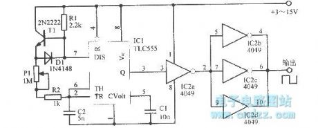
50% duty cycle oscillator is shown as figure.
(View)
View full Circuit Diagram | Comments | Reading(1158)
4 ~ 4.6MHz tuner
Published:2013/3/25 2:18:00 Author:Ecco | Keyword: 4 ~ 4.6MHz tuner
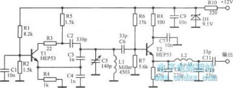
4 ~ 4.6MHz tuner is shown as figure.
(View)
View full Circuit Diagram | Comments | Reading(598)
20kHz multivibrator circuit
Published:2013/3/25 2:13:00 Author:Ecco | Keyword: 20kHz multivibrator
20kHz multivibrator circuit is shown as figure.
(View)
View full Circuit Diagram | Comments | Reading(1336)
1μs pulse circuit
Published:2013/3/25 2:16:00 Author:Ecco | Keyword: 1μs pulse
1μs pulse circuit is shown as figure.
(View)
View full Circuit Diagram | Comments | Reading(1117)
MOS FET unsteady state circuit
Published:2013/3/25 2:15:00 Author:Ecco | Keyword: MOS FET, unsteady state

MOS FET unsteady state circuit is shown as figure.
(View)
View full Circuit Diagram | Comments | Reading(607)
Closed-loop three-phase multivibrator
Published:2013/3/25 2:08:00 Author:Ecco | Keyword: Closed-loop , three-phase multivibrator
Closed-loop three-phase multivibrator is shown as figure.
(View)
View full Circuit Diagram | Comments | Reading(1021)
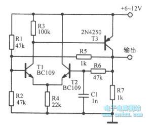
Light-emitting diode drived by the basic monostable circuit
Published:2013/3/25 2:52:00 Author:Ecco | Keyword: Light-emitting diode , basic monostable circuit
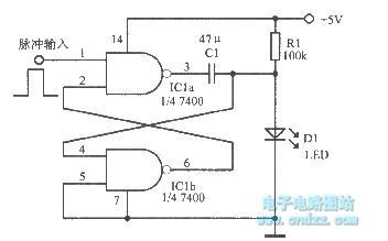
Light-emitting diode drived by the basic monostable circuit is shown as figure.
(View)
View full Circuit Diagram | Comments | Reading(1091)
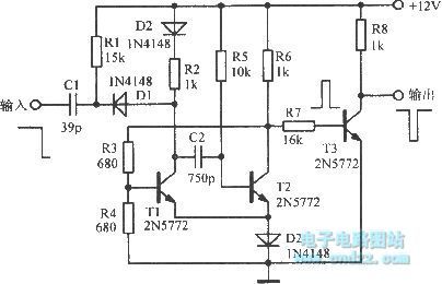
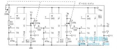
Wideband square wave oscillator with 50% duty cycle
Published:2013/3/25 2:50:00 Author:Ecco | Keyword: Wideband square wave, oscillator, 50% duty cycle
Wideband square wave oscillator with 50% duty cycle is shown as figure.
(View)
View full Circuit Diagram | Comments | Reading(1129)
Simple 12 Volt Battery charger
Published:2013/3/22 4:02:00 Author:Ecco | Keyword: 12 Volt Battery charger
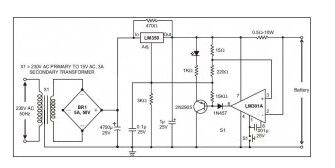
This kind of battery charger circuit will quickly and easily recharge almost every lead acid battery pack.This battery charger supplies maximum current till the current drawn by the battery falls to 150 miliamper. At this point, less voltage will be applied to complete and avoid over charging. Once the lead acid battery is completely charged, this circuit goes off and lights up the led, showing that the battery has completed to be charged.
(View)
View full Circuit Diagram | Comments | Reading(2816)
12V to 220V 100W Inverter
Published:2013/3/22 4:01:00 Author:Ecco | Keyword: 100W Inverter

If we want to work with the electrical equipment outsite home that has a voltage 220Volt /AC 50HZ, that only have around 100Watt not exceed. Yo need Small power inverter around 100Watt. This inverter perform modify from work electrical power forces of electric battery 12 volt provide high voltage to work.
(View)
View full Circuit Diagram | Comments | Reading(2595)
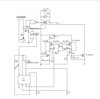
Mobile Charger with Voltage Converter
Published:2013/3/22 4:00:00 Author:Ecco | Keyword: Mobile Charger , Voltage Converter

The circuit allows a simple and safe charging of 1-10 Ni-Cd or Ni-MH cells from a 12V source. The voltage converter can be operated at 6V, in this case is the max. output voltage 12V (no load). The performance can be improved through the use of Schottky diodes (D2/D3). D4 (LED) can omitted if you dont want any indicator. An astable Mutivibrator generates the oscillation frequency. At the output (pin 3) connected the voltage doubler. At C5 is idling roughly double the input voltage. Thus, sufficient voltage difference exists to charge the connected batteries.Due to the high Switching frequency can be used relatively small capacitors. The charge current is indicated by a “real” load control (D4).
(View)
View full Circuit Diagram | Comments | Reading(1578)
+15 Volt 1 Amp Regulated Power Supply
Published:2013/3/22 3:59:00 Author:Ecco | Keyword: +15 Volt, 1 Amp, Regulated Power Supply

The actual supply takes +20 Volt Dc through the dioda bridge or filter part. This can be given to pins 11 and 12 on ua723, and also for the collector 2N3055 series-pass transistor. All the output voltage will be sampled through R1 and R2, giving around 7 Volt relating to ground at pin 4. The reference terminal at pin 6 is linked right to pin 5, the noninverting input of the error amplifier.
(View)
View full Circuit Diagram | Comments | Reading(1369)
-15 V 1-A Regulated Power Supply
Published:2013/3/22 3:59:00 Author:Ecco | Keyword: -15 V, 1-A , Regulated Power Supply
The actual supply should get -20 V coming from rectifier/filter that is given to the collector of Darlington PNP-type pass transistor, a TIP 105. The base drive for the TIP105 is supplied via resistor R5. The base of the TIP is driven from Vz terminal at pin 9, this is anode of 6.2 V zener diode which links with the emitter of uA 723 output control transistor. The way of providing the positive feedback needed for feedback action is shown.
(View)
View full Circuit Diagram | Comments | Reading(0)
12 Volt Battery charger
Published:2013/3/22 3:58:00 Author:Ecco | Keyword: 12 Volt, Battery charger
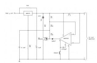
The following schematic is a high-performance battery charger for gelled electrolyte lead acid battery. Battery charger quickly recharges lead acid battery and shuts off at a full charge. Innitially, charging current has limitations to 2 Ampere. While the battery voltage goes up, current to the lead acid battery decrease, and if the current has decrease to 150 mA, the battery charger changes to a lower float voltage protecting against overcharge.
(View)
View full Circuit Diagram | Comments | Reading(1706)
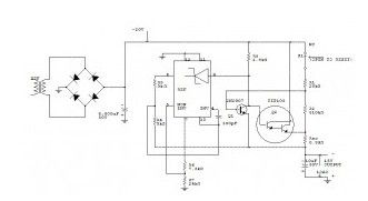
12 VDC TO 117 VAC / 60HZ POWER INVERTER
Published:2013/3/22 3:57:00 Author:Ecco | Keyword: 12 VDC TO 117 VAC , 60HZ , POWER INVERTER
Capacitor C5 and potentiometer R12 figure out the frequency of the output signal at pin number 3 of IC1, the 555oscillator. The output signal is differentiated by C3 and C4 before it’s input to the base of powertransistors Q1 and Q2 through diodes D1 and D2, respectively. The signal from IC1 is adjusted to 120 Hertz,because the flip-flop created by transistors Q3 and Q4 splits the frequency by two.
(View)
View full Circuit Diagram | Comments | Reading(1340)
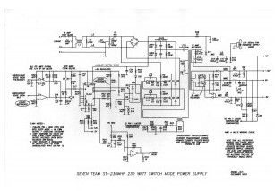
230W Switching Power Supply
Published:2013/3/22 3:56:00 Author:Ecco | Keyword: 230W, Switching Power Supply
View full Circuit Diagram | Comments | Reading(1733)
| Pages:138/2234 At 20121122123124125126127128129130131132133134135136137138139140Under 20 |
Circuit Categories
power supply circuit
Amplifier Circuit
Basic Circuit
LED and Light Circuit
Sensor Circuit
Signal Processing
Electrical Equipment Circuit
Control Circuit
Remote Control Circuit
A/D-D/A Converter Circuit
Audio Circuit
Measuring and Test Circuit
Communication Circuit
Computer-Related Circuit
555 Circuit
Automotive Circuit
Repairing Circuit