
Circuit Diagram
Index 136
DOD Overdrive 250
Published:2013/3/26 3:10:00 Author:Ecco | Keyword: DOD Overdrive 250
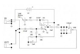
This is the DOD Overdrive 250 preamp circuit diagram. The DOD Overdrive 250 is Yet Another 741 With Two Diodes On The Output channel. It is almost exactly the same as the MXR Distortion Plus, and a number of other units.
(View)
View full Circuit Diagram | Comments | Reading(1248)
Stereo Tube Amplifier 4 Watts
Published:2013/3/26 3:09:00 Author:Ecco | Keyword: Stereo Tube Amplifier, 4 Watts

This is the circuit diagram of stereo tube amplifier using 6SQ7-GT and 6V6-GT. The tube amplifier circuit is uses the total of 5 power vacuum tube. The diagram is based on the output section design of typical late 1940′s old AM Trutone radio with 6 tubes. The output will be 4 Watts per channel (2x4W stereo tube amplifier)
(View)
View full Circuit Diagram | Comments | Reading(1443)
LM4809 Stereo 105mW Headphone Amplifier
Published:2013/3/26 3:07:00 Author:Ecco | Keyword: Stereo, 105mW, Headphone Amplifier
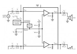
This is the stereo headphone amplifier circuit diagram, built based LM4809. This circuit can be used for stereo headphone amplifier circuit for home audio system, microphone preamplifier, personal computers and PDA headphone amplifier and more. The LM4809 is known as a stereo audio power amplifier capable of delivering 105mW per channel of continuous average power into a 16O load with 0.1% (THD+N) from a 5V power supply.
(View)
View full Circuit Diagram | Comments | Reading(859)
Tube Sound Fuzz
Published:2013/3/26 3:05:00 Author:Ecco | Keyword: Tube Sound Fuzz

This Tube Sound Fuzz circuit is taken from the book of Electronic Projects for Musicians by Craig Andertons. This circuit applies a CD4049 Hex inverter, which consists of six inverting units, only two are being used in this circuit, so the others are disabled by connecting their inputs to the positive voltage source and leaving the output disconnected.
(View)
View full Circuit Diagram | Comments | Reading(1254)
Western Music Generator based IC HT82207
Published:2013/3/26 3:05:00 Author:Ecco | Keyword: Western Music Generator

This is the schematic diagram of Western music generator circuit based on single IC HT82207. This circuit is able to take you towards the world of the Wild West. The western music already programmed in the chip. It utilizes the integrated 18-pin HT82207 (IC1) of Holtek, which literally takes care of almost everything.
(View)
View full Circuit Diagram | Comments | Reading(1351)
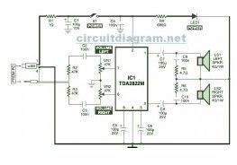
1W Stereo Headphone Amplifier based TDA2822
Published:2013/3/26 3:04:00 Author:Ecco | Keyword: 1W, Stereo Headphone Amplifier
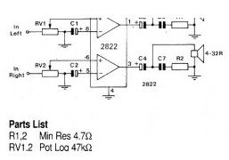
Above circuit diagram is the schematic of 1W stereo headphone amplifier. The circuit is built based TDA2822, designed for use in portable players, radios and other common electronic devices which can use headphone for the audio output.
(View)
View full Circuit Diagram | Comments | Reading(1881)
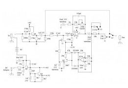
Hi-Fi Compressor with Pre-emphasis
Published:2013/3/26 3:03:00 Author:Ecco | Keyword: Hi-Fi Compressor, Pre-emphasis
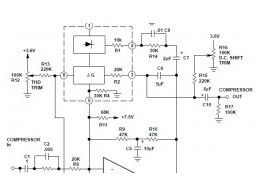
Here is the Hi-Fi compressor circuit with pre-emphasis. The above diagram is a circuit for a high fidelity compressor which uses an external op-amp and has a high gain and wide bandwidth. An input compensation network is required for stability.
(View)
View full Circuit Diagram | Comments | Reading(0)
4W Bridge Amplifier using LM388
Published:2013/3/26 3:02:00 Author:Ecco | Keyword: 4W Bridge Amplifier
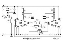
Parts List: R1-2-4-5=270Ω R3 = 2.7Ω VR1 = 10KΩ Log. Pot. TR1 = 470KΩ Trimmer IC1-2 = LM388 C1 = 100uF/25V C2 = 100nF C3 = 10uF/25V C4-5 = 22uF/25V C6 = 47nF.
(View)
View full Circuit Diagram | Comments | Reading(924)
65W Power Amplifier using HEXFET
Published:2013/3/26 3:01:00 Author:Ecco | Keyword: 65W Power Amplifier , HEXFET
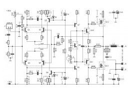
This is a high quality 65W power amplifier circuit based HEXFET IRF9540 and IRF540. The circuit is quite simple for amplifier with good sound quality. The component parts is easy to find at electronic store around your place. It uses split power supply. Q8, Q10, Q11, Q12, Q13 should be mounted on heatsink for thermic stability.
(View)
View full Circuit Diagram | Comments | Reading(2019)
1500W Power Amplifier
Published:2013/3/26 3:01:00 Author:Ecco | Keyword: 1500W, Power Amplifier
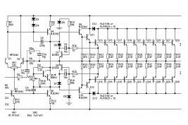
This is a very high 1500W power amplifier circuit diagram by Rod Elliott. The circuit is built using 10 pairs of power transistor MJ15024 and MJ15025 (or MJ21193/MJ21194), then it will use 20 pieces of power transistor for final amplification.
(View)
View full Circuit Diagram | Comments | Reading(3927)
150W Power Amplifier
Published:2013/3/26 3:00:00 Author:Ecco | Keyword: 150W , Power Amplifier
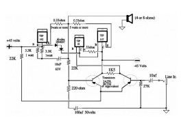
This is the very simple circuit diagram of 150W power amplifier. The circuit is easy enough to built without PCB. The power output range is about 100-150W depends to the power supply and the Darlington’s you use for the amplifier. Heatsink is a must since the final transistor is going to hot when the amplifier is activated.
(View)
View full Circuit Diagram | Comments | Reading(1676)
Electro-Harmonix Soul Preacher
Published:2013/3/26 2:59:00 Author:Ecco | Keyword: Electro-Harmonix Soul, Preacher
This is the circuit diagram of Electro-Harmonix Soul Preacher pedal.
(View)
View full Circuit Diagram | Comments | Reading(957)
Mic Condenser Amplifier
Published:2013/3/25 4:31:00 Author:Ecco | Keyword: Mic Condenser Amplifier
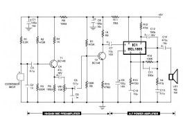
This is the circuit diagram of mic condenser amplifier. The low-cost and compact mic condenser audio amplifier described right here is deliver good-quality audio of 0.5 watts at 4.5 volts. It could possibly be applied as a part of low-power transmitters, packet radio receivers, intercoms and walkie-talkies.
(View)
View full Circuit Diagram | Comments | Reading(1146)
Cheap Hearing Aid
Published:2013/3/25 4:30:00 Author:Ecco | Keyword: Cheap Hearing Aid
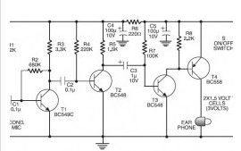
Here the cheap hearing aid to help people who have hearing loss. Commercially available assistive hearing devices are quite expensive. This is a cheap hearing aid device circuit which works by using just four transistors and several passive electronic components.
(View)
View full Circuit Diagram | Comments | Reading(883)
Ticking Bomb Sound Generator
Published:2013/3/25 4:29:00 Author:Ecco | Keyword: Ticking Bomb, Sound Generator
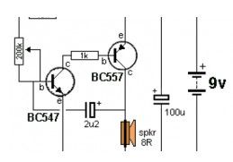
Here the low cost and easy build circuit of ticking bomb sound generator. This circuit generates a sound matching to a loud clicking clock. The frequency of the tick is altered through the 220k potensiometer part. The circuit gets going by charging the 2.2uF and when 0.65v is on the base of the NPN transistor, it begins to turn on
. (View)
View full Circuit Diagram | Comments | Reading(1001)
Electronic Horn
Published:2013/3/25 4:29:00 Author:Ecco | Keyword: Electronic Horn
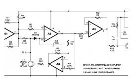
This is an easy, low cost and easy built circuit of an electronic horn which is designed close to quadruple op-amp IC LM3900 (IC1). IC LM3900 has four independent operational-amplifiers (A1 through A4) having a large output voltage swing. It is able to operate at up to 32V DC. (View)
View full Circuit Diagram | Comments | Reading(869)
USB Powered, Stereo Computer Speaker
Published:2013/3/25 4:27:00 Author:Ecco | Keyword: USB Powered, Stereo Computer Speaker
View full Circuit Diagram | Comments | Reading(876)
Stereo Digital Volume Control
Published:2013/3/25 4:26:00 Author:Ecco | Keyword: Stereo Digital, Volume Control
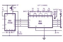
Here is the circuit diagram of stereo digital volume control. This circuit could possibly be applied for upgrading your manual volume management within a stereo amplifier circuit. In this particular circuit, push-to-on switch S1 controls the forward (volume enhance) operation of the two channels while a identical switch S2 controls reverse (volume reduce) operation of the two channels.
(View)
View full Circuit Diagram | Comments | Reading(3785)
Touch Alarm System
Published:2013/3/25 4:25:00 Author:Ecco | Keyword: Touch Alarm System

Touch Alarm circuit is widely used for security, which is installed on the door. The advantages of this alarm is because the cost is cheap and difficult to detect by burglars / intruders.
(View)
View full Circuit Diagram | Comments | Reading(1632)
Sound Effect Generator UM3561
Published:2013/3/25 4:17:00 Author:Ecco | Keyword: Sound Effect Generator
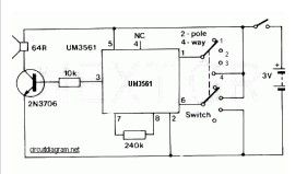
This is a really simple sound effect generator based single sound generator chip UM3561. The UM3561 will generate four kinds of sound effects. The basic operation is that the UM3561 will generate the sound signal, then the signal delivered to 2N3706 (as speaker driver) to be amplified so you can hear the sound from a speaker.
(View)
View full Circuit Diagram | Comments | Reading(843)
| Pages:136/2234 At 20121122123124125126127128129130131132133134135136137138139140Under 20 |
Circuit Categories
power supply circuit
Amplifier Circuit
Basic Circuit
LED and Light Circuit
Sensor Circuit
Signal Processing
Electrical Equipment Circuit
Control Circuit
Remote Control Circuit
A/D-D/A Converter Circuit
Audio Circuit
Measuring and Test Circuit
Communication Circuit
Computer-Related Circuit
555 Circuit
Automotive Circuit
Repairing Circuit