
Circuit Diagram
Index 134
Theremin Music Instrument
Published:2013/3/27 3:50:00 Author:Ecco | Keyword: Theremin Music Instrument
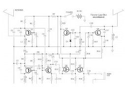
The following diagram is the Theremin music instrument effect. A guitar or instrument amplifier is an ideal companion unit for the theremin; either one allows bass or treble boost, as desired, and fuzz (distortion) or reverberation (if these features are incorporated in the amplifier’s circuit). Simply provide a suitable cable plug and connect the theremin’s output cable to the amplifier’s input jack.
(View)
View full Circuit Diagram | Comments | Reading(876)
Tone Booster
Published:2013/3/27 3:49:00 Author:Ecco | Keyword: Tone Booster

Below circuit is the tone booster circuit. According to the name of circuit, the purpose is to gain the sound signal to become more powerful in both low and high frequencies. Transistor type: Q1 – ztx384 ; Q2 – BC415p The circuit’s peaks frequencies is at 5000 Hz for a cleaner and more penetrating sound.
(View)
View full Circuit Diagram | Comments | Reading(1252)
Tube Distortion Pedal
Published:2013/3/27 3:49:00 Author:Ecco | Keyword: Tube Distortion Pedal
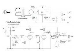
The following circuit is Tube Distortion Pedal for guitar effect. The circuit designed by Ron Black. Notes: IC1 : 747 dual op-amp, other ICs may be substitued but pinout will different. You should check the datasheet IC2 : LM340K-12V Voltage Regulator All resistors are 1/2 W Bridge Rectifier – Full wave bridge recitifier, 50 Volts, 500 mA minimum.
(View)
View full Circuit Diagram | Comments | Reading(1217)
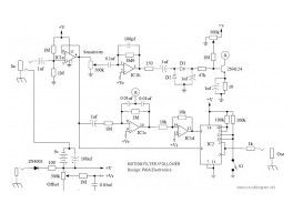
Surround Sound Decoder
Published:2013/3/27 3:48:00 Author:Ecco | Keyword: Surround Sound Decoder
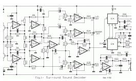
The following diagram is an small surround sound decoder schematics. You may use this decoder surround sound systems for your home audio system. Parts List: R1-2-7-8-12-13-18-19-20=47Kohm R3-4-5-6-21-22-34-35=10Kohm R9-10-11-14-15-16-17=15Kohm R=23-24-25-33-36=100ohm R26-27-28-31-32=100Kohm R29-30=5.6Kohm C1-8=47uF 25V C2-7-9-14-23=47nF 100V C3-6=1uF 100V C4-5-10=33pF 100V C11-12-15=10uF 25V C13=82nF C16=18pF 100V C17=100pF mini adjustable capacitor C18=2.2nF C19=4.7uF 25V C20=100nF 100V C21=10nF C22=180pF C24=150nF RV1-RV2=2X10Kohm Log. pot. RV3-4=10K Log pot. D1=1N4148 IC1-6=TL072 IC2-3=TL074 IC4=MN3101 IC5=MN3004 JI…..J6=RCA female jack
(View)
View full Circuit Diagram | Comments | Reading(985)
VOX Treble Booster
Published:2013/3/27 3:47:00 Author:Ecco | Keyword: VOX Treble Booster
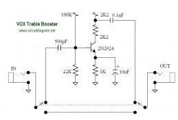
The following diagram is the circuit diagram of VOX Treble Booster. Vox made a variety of boosters that were meant to be plugged directly into amplifiers or guitars. Original VOX Treble Booster diagram:
(View)
View full Circuit Diagram | Comments | Reading(1107)
20W Power Tube Amplifier with EL34
Published:2013/3/27 3:46:00 Author:Ecco | Keyword: 20W , Power Tube, Amplifier
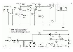
The following diagram is the circuit diagram of 20W power amplifier which build based tube component EL34. EL34 is very famous tube and great for power tube amplifier. The circuit above is complete circuit contains tube amplifier circuit diagram and power supply circuit diagram. To make the stereo channel amplifier, build the similar amplifier circuit only and connect to the power supply using parallel connection with another same amplifier.
(View)
View full Circuit Diagram | Comments | Reading(2009)
Distortion Booster
Published:2013/3/27 3:45:00 Author:Ecco | Keyword: Distortion Booster
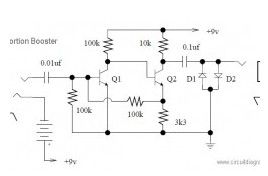
The following circuit is an distortion booster effect for your electric guitar. I don’t know whether this circuit is really works or not, you may try this circuit with your own risk. Circuit notes: Q1 and Q2 are BC108 D1 and D2 are silicon or germanium (pick your favorite flavor) signal diodes.
(View)
View full Circuit Diagram | Comments | Reading(896)
A/B Box Guitar Effect Schematic
Published:2013/3/27 3:45:00 Author:Ecco | Keyword: A/B Box Guitar Effect
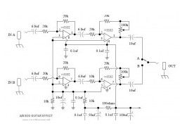
This is a A/B Box pedal schematic for electric guitar was designed by Rick Barker. This A/B Box effect was originally designed for switching between different harmonica mics. This A/B Box featured low noise dual preamp for better effect.
(View)
View full Circuit Diagram | Comments | Reading(1107)
Simple Mixer
Published:2013/3/27 3:44:00 Author:Ecco | Keyword: Simple Mixer

Here the simple mixer with 4 input and 2 op-amps: A basic mixer suitable for mixing microphones or even effects outputs. The overall gain from input to output is one if the pot related towards the input is full up. You can make this a net gain of ten (or any other reasonable gain) by reducing the input resistor towards the second op amp.
(View)
View full Circuit Diagram | Comments | Reading(1596)
Guitar Pre-Amp with JFET 2N5457
Published:2013/3/27 3:43:00 Author:Ecco | Keyword: Guitar Pre-Amp , JFET
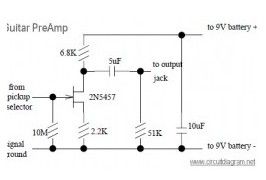
Designed by Don Tillman, this guitar pre-amp circuit design is dedicated for people who don’t like op-amps. This circuit is a discrete JFET pre-amp design, use 2N5457 as the main component. It has low noise, low distortion, low feedback, overloads gracefully, is small, etc.
(View)
View full Circuit Diagram | Comments | Reading(2850)
Maestro Boomerang
Published:2013/3/27 3:43:00 Author:Ecco | Keyword: Maestro Boomerang
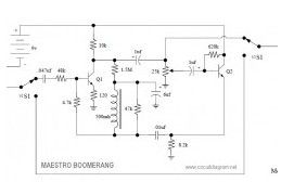
Here the circuit diagram of Maestro Boomerang / Wah-Wah Pedal for electric guitar effect. Note: Transistors Q1 and Q2 were designated P-2356
(View)
View full Circuit Diagram | Comments | Reading(722)
Simple Mic Pre-Amp based LM358
Published:2013/3/27 3:42:00 Author:Ecco | Keyword: Simple Mic Pre-Amp
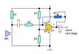
Here the simple audio mic pre amplifier circuit based on single IC LM358. The circuit is very simple, inexpensive and easy to built. Component Parts List: R1, R3, R4 = 10K R2 = 1K R5 = 100K-1M Potensiometer C1 = 0.1uF C2 = 4.7uF/16V IC1 = LM358 dual op-amp single supply Mic = Electret Microphone
(View)
View full Circuit Diagram | Comments | Reading(2440)
Dallas Arbiter Fuzz Face
Published:2013/3/27 3:41:00 Author:Ecco | Keyword: Dallas Arbiter Fuzz Face
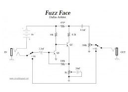
This is the circuit diagram of Fuzz Face mods, guitar effect pedal. This is a modified diagram and simpler than the original Fuzz Face diagram. You will find apparently two identical designs of the fuzz face. In one Q1 and Q2 had been PNP germanium AC128 or NKT275 types, in the other they had been NPN sillicon BC108C types.
(View)
View full Circuit Diagram | Comments | Reading(1137)
Jimi Hendrix Fuzz Face Pedal
Published:2013/3/27 3:40:00 Author:Ecco | Keyword: Jimi, Hendrix Fuzz Face Pedal
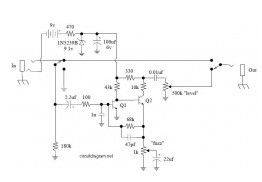
The following diagram is the Jimi Hendrix Fuzz Face Pedal circuit diagram. Schematic by Jim Dunlop Note: Q1 & Q2 are MPSA18.
(View)
View full Circuit Diagram | Comments | Reading(1168)
Motion Filter Effect
Published:2013/3/27 3:40:00 Author:Ecco | Keyword: Motion Filter Effect
This circuit will controls the initial frequency and controls how much the envelope follower responds to the input signal. An envelope follower/filter combination translates the typical dynamic properties of your axe into modulated timbral changes too, you could feel of it as an automatic wah-wah pedal.
(View)
View full Circuit Diagram | Comments | Reading(620)
Mesa Boogie Dual Rectifier
Published:2013/3/27 3:39:00 Author:Ecco | Keyword: Mesa Boogie , Dual Rectifier
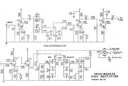
The following diagram is Dual Rectifier schematic diagram. This is a tubed pre-amp and tubed amplifier designed and manufactured by Mesa Boogie. This Mesa Boogie Dual Rectifier available to download in pdf document. You will find the complete diagram of this dual rectifier there.
(View)
View full Circuit Diagram | Comments | Reading(2716)
The self-excited multivibrator with improving waveform and stability
Published:2013/3/27 3:29:00 Author:Ecco | Keyword: self-excited multivibrator , improving waveform , stability
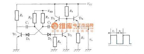
The self-excited multivibrator with improving waveform and stability is shown as figure.
(View)
View full Circuit Diagram | Comments | Reading(976)
Four monostable circuit
Published:2013/3/25 2:42:00 Author:Ecco | Keyword: Four monostable, circuit
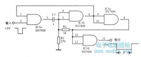
Four monostable circuit is shown as figure.
(View)
View full Circuit Diagram | Comments | Reading(594)
Zener diode controlled Wien bridge
Published:2013/3/25 2:48:00 Author:Ecco | Keyword: Zener diode , Wien bridge
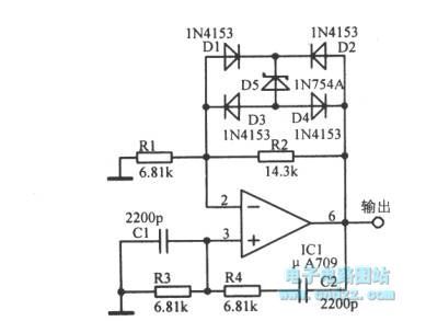
Zener diode controlled Wien bridge is shown as figure.
(View)
View full Circuit Diagram | Comments | Reading(1565)
Square wave burst
Published:2013/3/27 3:30:00 Author:Ecco | Keyword: Square wave burst

Square wave burst is shown as figure.
(View)
View full Circuit Diagram | Comments | Reading(1279)
| Pages:134/2234 At 20121122123124125126127128129130131132133134135136137138139140Under 20 |
Circuit Categories
power supply circuit
Amplifier Circuit
Basic Circuit
LED and Light Circuit
Sensor Circuit
Signal Processing
Electrical Equipment Circuit
Control Circuit
Remote Control Circuit
A/D-D/A Converter Circuit
Audio Circuit
Measuring and Test Circuit
Communication Circuit
Computer-Related Circuit
555 Circuit
Automotive Circuit
Repairing Circuit