
Circuit Diagram
Index 130
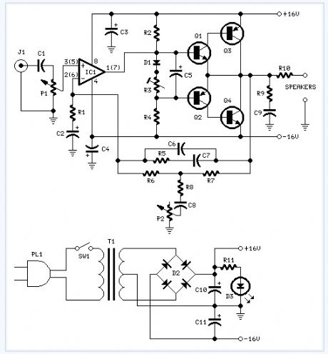
18w Audio Amplifier electronic circuit
Published:2013/4/1 2:36:00 Author:Ecco | Keyword: 18w Audio Amplifier

Amplifier parts: P1 = 22K Log.Potentiometer (Dual-gang for stereo)R1 = 1K 1/4W ResistorR2 = 4K7 1/4W ResistorR3 = 100R 1/4W ResistorR4 = 4K7 1/4W ResistorR5 = 82K 1/4W ResistorR6 = 10R 1/2W ResistorR7 = R22 4W Resistor (wirewound)R8 = 1K 1/2W Trimmer Cermet (optional)C1 = 470nF 63V Polyester CapacitorC2,C5 = 100΅F 3V Tantalum bead CapacitorsC3,C4 = 470΅F 25V Electrolytic CapacitorsC6 = 100nF 63V Polyester CapacitorD1 = 1N4148 75V 150mA DiodeIC1 = TLE2141C Low noise,high voltage,high slew-rate Op-ampQ1 = BC182 50V 100mA NPN TransistorQ2 = BC212 50V 100mA PNP TransistorQ3 = TIP42A 60V 6A PNP TransistorQ4 = TIP41A 60V 6A NPN TransistorJ1 RCA audio input socket
(View)
View full Circuit Diagram | Comments | Reading(1526)
15 Watt Amplifier electronic circuit
Published:2013/4/1 2:35:00 Author:Ecco | Keyword: 15 Watt Amplifier

This amplifier uses a dual 20 Volt power supply and delivers 15 watts RMS into an 8 ohm load. Q1 operates in common emitter, the input signal being passed to the bias chain consisting of Q8, Q9, D6, D13 and D14. Q8 and Q9 provide a constant current through the bias chain to minimize distortion, the output stage formed by a discrete darlington pair (Q2,Q4) and (Q7,Q11). The last two transistors are power Transitors, specifically the 2N3055 and MJ2955. The 7.02K resistor, R16 was made using a series combination of a 4.7K, 680 Ohms, and two 820 Ohms. The 1.1K resistor, R3 was made using a 100 Ohms and a 1K resistor. You can use this circuit with any walkman or CD player since it is designed to take a standard 500mv RMS signal.
(View)
View full Circuit Diagram | Comments | Reading(879)
10w Audio Amplifier With Bass-boost electronic circuit
Published:2013/4/1 2:35:00 Author:Ecco | Keyword: 10w Audio Amplifier, Bass-boost
This design is based on the 18 Watt Audio Amplifier, and was developed mainly to satisfy the requests of correspondents unable to locate the TLE2141C chip. It uses the widespread NE5532 Dual IC but, obviously, its power output will be comprised in the 9.5 - 11.5W range, as the supply rails cannot exceed ±18V.As amplifiers of this kind are frequently used to drive small loudspeaker cabinets, the bass frequency range is rather sacrificed. Therefore a bass-boost control was inserted in the feedback loop of the amplifier, in order to overcome this problem without quality losses. The bass lift curve can reach a maximum of +16.4dB @ 50Hz. In any case, even when the bass control is rotated fully counterclockwise, the amplifier frequency response shows a gentle raising curve: +0.8dB @ 400Hz, +4.7dB @ 100Hz and +6dB @ 50Hz (referred to 1KHz).
(View)
View full Circuit Diagram | Comments | Reading(1468)
10w Mini Audio Amplifier electronic circuit
Published:2013/4/1 2:34:00 Author:Ecco | Keyword: 10w, Mini Audio Amplifier
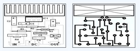
You can use this powerfull amplifier in any small audio project. It is very small (6.5 x 4.5 cm).It outputs 10W and uses a 9V battery.
(View)
View full Circuit Diagram | Comments | Reading(1490)
LT1020 Battery Backup Regulator circuit
Published:2013/3/29 4:44:00 Author:Ecco | Keyword: Battery Backup Regulator
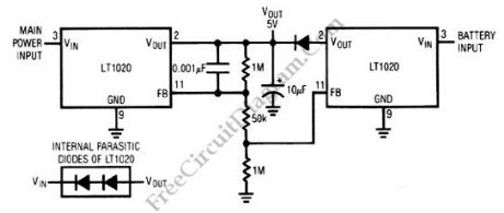
A low-loss way to implement a”glitch-free” battery backup for a memory or similar circuit is shown on the following schematic diagram. To make LT1020 does not conduct under line-powered conditions, we have to arrange the feedback string. The line LT1020 begins to go off when the lie goes down, which allows the battery-driven LT1020 to turn on and maintain the load.
(View)
View full Circuit Diagram | Comments | Reading(1047)
Remote Sensor System Pre-Amp circuit
Published:2013/3/29 4:43:00 Author:Ecco | Keyword: Remote Sensor System, Pre-Amp

Remote sensor might cause a trouble if it’s a passive type, has very low power output, and should be connected with relatively long cables. By supplying a current or voltage source through its connection wire, it’s possible to make long enough wiring without suffering much noise/interference. The following schematic diagram show a circuit consist of LM10 to make a remote vibration sensor connection works fine. We don’t need a separate wires for signal and power supply, we send them on the same cable pair! Here is the schematic diagram of the circuit:
(View)
View full Circuit Diagram | Comments | Reading(1074)
Monitoring Off-Air Condition
Published:2013/3/29 4:43:00 Author:Ecco | Keyword: Monitoring Off-Air Condition
The circuit of off-air monitor for SSB transmitter can be built by using combination of detector product with the crystal oscillator. This circuit is used for testing the audio at one point within band. The quality of audio will still constant, if loading and tuning of SSB transmitter are same over rest of band. The LC circuit will resonated to band being used. When the transceiver is in receive mode, this circuit will spot the oscillator signal. And if the transceiver transmit the signal, the transceiver can be monitored. Here is the schematic diagram of the circuit:
(View)
View full Circuit Diagram | Comments | Reading(663)
Audio-Controlled Incandescent Lamp Light Controller circuit
Published:2013/3/29 4:42:00 Author:Ecco | Keyword: Audio-Controlled , Incandescent Lamp Light, Controller
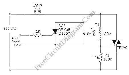
This is a audio-controlled lamp circuit. This circuit requires low voltage input such as pre-amplifiers, tone control, or general audio line level output. It’s also possible to feed the input with signal from small power amplifier output, or high power amplifier witk low volume level. The characteristic of lamp dimming (incandescent lamp) will look like coming from proportional controller since the switching rate of the TRIAC would be much higher than the lamp dimming response. Here is the schematic diagram of the circuit:
(View)
View full Circuit Diagram | Comments | Reading(1695)
Power Amplifier’s Overload/Clipping Indicator circuit
Published:2013/3/29 4:41:00 Author:Ecco | Keyword: Power Amplifier, Overload/Clipping Indicator

Clipping is a condition where a signal is truncated by insufficient processing. The cause of clipping can be different for various case, but most of them, especially in power amplifier stage, is because the amplifier is forced to serve out-range of power when the input volume is too high. Detecting severely clipped signal is easy by listening, but a soft clipping might be hard to detect. The problem is that some people might notice and some might not. Because our perception of slightly clipped signal might be inconsistent depending on our mood and our mental focus, providing a clipping indication will be very useful for those who responsible in sound performance. This circuit will give visual indicator, the led will light, when the output reach 50Watt level (can be adjusted with R2 pot). Here is the schematic diagram of the circuit.
(View)
View full Circuit Diagram | Comments | Reading(2434)
Chromel Alumel Thermocouple Current Loop Transmitter circuit
Published:2013/3/29 4:41:00 Author:Ecco | Keyword: Chromel Alumel, Thermocouple Current Loop , transmitter

The schematic diagram below show signal conditioning circuit for remote current loop temperature transmitter. This thermocouple temperature transmitter is loop powered, means it doesn’t need its own power supply since the supply is provided by the current loop receiver. Thermocouple is basically a junction of two different metallic material that measures the temperature difference.
(View)
View full Circuit Diagram | Comments | Reading(1769)
Mixer or Sewing Machine Motor Speed Control circuit
Published:2013/3/29 4:39:00 Author:Ecco | Keyword: Mixer or Sewing Machine, Motor Speed Control

It will be effective to use simple half wave motor speed control with small universal ac/dc motors. Two amps RMS is the maximum current capability. The control gives excellent torque characteristics to the motor because speed dependent feedback is provided, even at low rotation speeds. By closing switch S1, thus bypassing the SCR, we can achieve normal operation at maximum speed.
(View)
View full Circuit Diagram | Comments | Reading(3578)
Color-Shifting LED Show circuit
Published:2013/3/29 4:38:00 Author:Ecco | Keyword: Color-Shifting LED Show

This circuit gives a changing-color LED display, where a LED will emit a dynamic shifting color, from red to green smoothly through yellow. The circuit uses NE556 dual timer, equal to two 555 IC but in only one package. The oscillators is set at different frequencies. The high frequency (upper part) is used to construct a PWM signal, and the lower frequency oscillator is used to control the shifting frequency. What is done by the low frequency oscillator is no more than modulating the duty cycle (active factor) of the PWM.
(View)
View full Circuit Diagram | Comments | Reading(1180)
Single Cell Battery Meter Amplifier circuit
Published:2013/3/29 4:37:00 Author:Ecco | Keyword: Single Cell Battery , Meter Amplifier
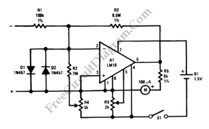
A meter amplifier can be designed using LM10 integrated circuit (IC). The accuracy of full-scale sensitivity is good for over 15°C to 155°C at 10mV and 100nA. Here is the schematic diagram of the circuit:
(View)
View full Circuit Diagram | Comments | Reading(1002)
5V FET Voltage Regulator circuit
Published:2013/3/29 4:35:00 Author:Ecco | Keyword: 5V FET Voltage Regulator
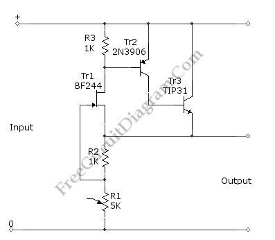
This voltage regulator circuit gives a stable 5V output from unregulated inputs (more than 5V). The stability of the output voltage is good enough, only change less than 0.1 volts when the load current changes about 60mA. Here is the schematic diagram of the circuit:
(View)
View full Circuit Diagram | Comments | Reading(1475)
General Purpose Alarm Circuit for Resistive Sensor circuit
Published:2013/3/29 4:35:00 Author:Ecco | Keyword: General Purpose Alarm , Resistive Sensor
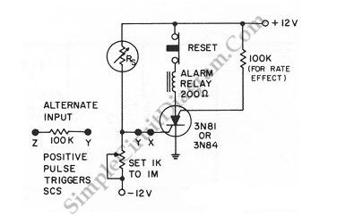
When the resistance value of a temperature, light, pressure, or any other resistive sensors Rs drops below a certain point (adjusted by a preset potentiometer), the SCR (silicon controlled switch) will be triggered. The sensor (Rs) and the potentiometer placement can be interchanged to get opposite action, where the SCR need to be triggered at the increase of sensing resistor (Rs). Here is the schematic diagram of the circuit:
(View)
View full Circuit Diagram | Comments | Reading(1230)
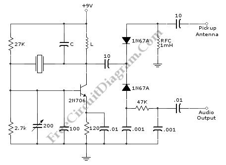
Active Antenna With Gain (Booster) circuit
Published:2013/3/29 4:34:00 Author:Ecco | Keyword: Active Antenna , Gain (Booster)

This is an active antenna circuit with gain. This circuit is used to bost the signal. This circuit is made from a few transistors and other components. This circuit can provide RF gain of about12 to 18 dB. This circuit uses Q2 as a voltage amplifier. the RF signal direct-coupled from Q1’s Source terminal to the base of Q2. The Q3 is configured as an emitter-fallower amplifier which match and isolate the gam stage from the receiver’s RF-inputcircuitry. Here is the schematic diagram of the circuit:
(View)
View full Circuit Diagram | Comments | Reading(1754)
26V-to-5000V DC-DC Converter circuit
Published:2013/3/29 4:34:00 Author:Ecco | Keyword: 26V-to-5000V, DC-DC Converter

This circuit can provide 5,000 VDC from 26 VDC. This circuit has ripple of under 0.01% due to Voltage-doubling capacitors. As sinusoidal oscillator, a 2N217 transistor is used. The diode and the capacitors at the output stage should be of high voltage type. Here is the schematic diagram of the circuit:
(View)
View full Circuit Diagram | Comments | Reading(2093)
Transceiver Saver (Overvoltage Protector) circuit
Published:2013/3/29 4:33:00 Author:Ecco | Keyword: Transceiver Saver, Overvoltage Protector
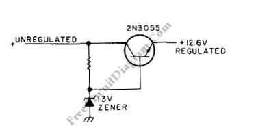
This is a transceiver saver circuit that protect a transceiver device (applicable to other device as well) from overvoltage of the power supply. This circuit is used to protect the device by regulating the power supply, avoiding damaging the device if overvoltage occurs. If the transceiver transmits current of above 2A, a heatsink should be used for the transistor. The value of resistor must provide output of 12.6 V during normal operation, you can make trial and error through measurement when choosing this., you can start with value around 100R. It’s recommended to use a high wattage Zener diode. Here is the schematic diagram of the circuit:
(View)
View full Circuit Diagram | Comments | Reading(609)
Voltage and Current Limited Audible Continuity Tester circuit
Published:2013/3/29 4:31:00 Author:Ecco | Keyword: Voltage and Current, Limited Audible, Continuity Tester
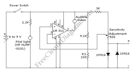
Using this continuity tester circuit, a failure of PCB tracks be examined without looking directly at the tracks routing, which is can be very frustrating. The indication of this circuit is done by an audible alarm (a buzzer). This circuit can be used to indicate continuity below any resistance value up to 35 ohms by adjusting the circuit. To make sure this circuit doesn’t damage any installed parts on the board, the voltage and current of this circuit is limited. Here is the schematic diagram of the circuit:
(View)
View full Circuit Diagram | Comments | Reading(1407)
Series-Wound Direction And Speed Motor Control circuit
Published:2013/3/29 4:30:00 Author:Ecco | Keyword: Series-Wound Direction , Speed Motor Control

This is a motor controller circuit that control the speed and direction of series-wound Motors. This circuit employs silicon controlled rectifiers (SCR) Q1-Q4, that are triggered in diagonal pairs. The switch St is used to control which pair is turned on because either coupling transformer T2 or coupling transformer T1 is connected to a pulsing circuit by this switch. Here is the schematic diagram of the circuit:
(View)
View full Circuit Diagram | Comments | Reading(1120)
| Pages:130/2234 At 20121122123124125126127128129130131132133134135136137138139140Under 20 |
Circuit Categories
power supply circuit
Amplifier Circuit
Basic Circuit
LED and Light Circuit
Sensor Circuit
Signal Processing
Electrical Equipment Circuit
Control Circuit
Remote Control Circuit
A/D-D/A Converter Circuit
Audio Circuit
Measuring and Test Circuit
Communication Circuit
Computer-Related Circuit
555 Circuit
Automotive Circuit
Repairing Circuit