Measuring and Test Circuit
Voltage and Current Limited Audible Continuity Tester circuit
Published:2013/3/29 4:31:00 Author:Ecco | Keyword: Voltage and Current, Limited Audible, Continuity Tester | From:SeekIC
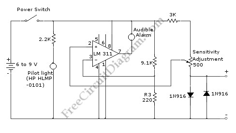
Using this continuity tester circuit, a failure of PCB tracks be examined without looking directly at the tracks routing, which is can be very frustrating. The indication of this circuit is done by an audible alarm (a buzzer). This circuit can be used to indicate continuity below any resistance value up to 35 ohms by adjusting the circuit. To make sure this circuit doesn’t damage any installed parts on the board, the voltage and current of this circuit is limited. Here is the schematic diagram of the circuit:
Reprinted Url Of This Article:
http://www.seekic.com/circuit_diagram/Measuring_and_Test_Circuit/Voltage_and_Current_Limited_Audible_Continuity_Tester_circuit.html
Print this Page | Comments | Reading(3)

Article Categories
power supply circuit
Amplifier Circuit
Basic Circuit
LED and Light Circuit
Sensor Circuit
Signal Processing
Electrical Equipment Circuit
Control Circuit
Remote Control Circuit
A/D-D/A Converter Circuit
Audio Circuit
Measuring and Test Circuit
Communication Circuit
Computer-Related Circuit
555 Circuit
Automotive Circuit
Repairing Circuit
Code: