
Circuit Diagram
Index 137
Easy Build Motorcycle Alarm
Published:2013/3/25 4:16:00 Author:Ecco | Keyword: Easy Build Motorcycle, Alarm

The following circuit is a simple, cheap and easy build motorcycle alarm. The circuit just required 2 transistors to drive the relay the the relay act as a switch to activate the buzzer. Any number of normally-open switches may possibly be applied.
(View)
View full Circuit Diagram | Comments | Reading(1335)
Beeper Sound
Published:2013/3/25 4:16:00 Author:Ecco | Keyword: Beeper Sound
This is the circuit diagram of beeper sound. The circuit will generate the sound of a beeper which similar with the one in pagers. It produces a “beep-beep” sound. The work of this circuit is simple, the circuit applied the 555 timer oscillator which is turned ON and OFF periodically.
(View)
View full Circuit Diagram | Comments | Reading(685)
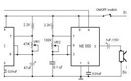
Electronic Siren based NE555
Published:2013/3/25 4:04:00 Author:Ecco | Keyword: Electronic Siren

Here the circuit diagram of electronic siren based NE555. This circuit produces a sound like factory siren. It applies a 555 timer IC which is utilized as an astable multivibrator of a center frequency of about 300Hz. The frequency is controlled by the pin 5 of the IC.
(View)
View full Circuit Diagram | Comments | Reading(1416)
LPG Gas Leakage Sensor Alarm
Published:2013/3/25 4:03:00 Author:Ecco | Keyword: LPG Gas Leakage, Sensor, Alarm
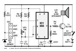
This is the schematic diagram of LPG gas leakage sensor alarm. The circuit operates off a 9V PP3 battery. Zener diode ZD1 is applied to convert 9V into 5V DC to drive the gas sensor module. The SEN-1327 gas sensor module from RhydoLABZ is applied in this circuit. Its output goes higher when the gas amount reaches or exceeds specific point.
(View)
View full Circuit Diagram | Comments | Reading(1901)
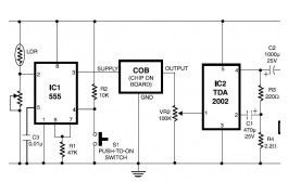
Adjustable Analog Timer
Published:2013/3/25 4:02:00 Author:Ecco | Keyword: Adjustable Analog Timer
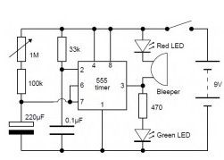
This is a very simple adjustable analog timer circuit diagram. You can build this circuit just for fun, for newbie project or may be…, this circuit could be used to set a time limit when playing games or as an egg-timer in the kitchen.
(View)
View full Circuit Diagram | Comments | Reading(2204)
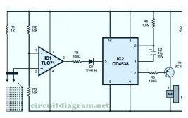
Pyroelectric Fire Alarm System
Published:2013/3/25 4:02:00 Author:Ecco | Keyword: Pyroelectric , Fire Alarm System

This is definitely an ultra-sensitive fire sensor that exploits the direct piezoelectric property of an ordinary piezo component to recognize the fire. The lead zirconate titanate crystals within the piezo component have the property to deform and produce an electrical potential when heated, thus converting the piezo component into a heat sensor.
(View)
View full Circuit Diagram | Comments | Reading(1126)
Multitone Siren Alarm
Published:2013/3/25 4:01:00 Author:Ecco | Keyword: Multitone Siren Alarm
Here the simple schematic of multitone siren alarm circuit. This multitone siren is effective for reverse horns, burlgar alarms, and many others. It generates five various audio tones and is much more earcatching than a single-tone siren.
(View)
View full Circuit Diagram | Comments | Reading(1401)
Heat Detector + Siren
Published:2013/3/25 3:49:00 Author:Ecco | Keyword: Heat Detector, Siren
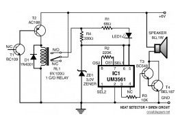
This is the diagram of heat detector circuit which already integrated with siren circuit in the output. This circuit applies a complementary pair comprising NPN metallic transistor T1 (BC109) and PNP germanium transistor T2 (AC188) to detect heat (because of outbreak of fire, for example) in the area and activate a siren/alarm.
(View)
View full Circuit Diagram | Comments | Reading(935)
Fire Alarm with LDR Sensor
Published:2013/3/25 3:48:00 Author:Ecco | Keyword: Fire Alarm , LDR Sensor
This is the fire alarm circuit which use LDR to sense the smoke from the fire, so it can be used to detect any dark smoke. With the onset of summer season, possibilities of fire accidents go up. These fire accidents could be prevented if timely alarms are available. The circuit given right here alerts the user against these fire accidents.
(View)
View full Circuit Diagram | Comments | Reading(1306)
Cheap Motorcycle Alarm
Published:2013/3/25 3:47:00 Author:Ecco | Keyword: Cheap Motorcycle Alarm

This is simple to build and cheap motorcycle alarm circuit which could be fitted in motorcycles to take care of them from getting stolen. The tiny circuit may be hidden anyplace, without having any difficult wiring. Practically, it fits all motorcycles as long as they’ve a electric battery.
(View)
View full Circuit Diagram | Comments | Reading(1204)
Automatic Switch-Off Staircase Light
Published:2013/3/25 3:47:00 Author:Ecco | Keyword: Automatic Switch-Off Staircase, Light

This is the circuit diagram of staircase light with automatic switch off. It based on timer which is can be adjusted with the needs of the time of walking (climbing up and going down) on the staircase.
(View)
View full Circuit Diagram | Comments | Reading(1690)
Shutter Guard
Published:2013/3/25 3:45:00 Author:Ecco | Keyword: Shutter Guard
This is the shutter guard circuit which has sensitive vibration sensor, piezo-sensor. This circuit is specifically designed for outlets to defend towards theft. It can recognize any mechanical or acoustic vibration in its area when somebody attempts to break the shutter and instantly turn on a lamp and sound an alert alarm.
(View)
View full Circuit Diagram | Comments | Reading(823)
Power Supply Failure Alarm
Published:2013/3/25 3:44:00 Author:Ecco | Keyword: Power Supply, Failure Alarm
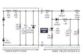
This is the ‘special’ circuit design of power supply failure alarm. The vast majority of the power supply failure alarm / indicator circuits require a independent power supply for themselves. However the alarm circuit introduced right here requires no extra supply power source.
(View)
View full Circuit Diagram | Comments | Reading(1048)
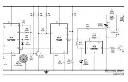
Musical Bell with Touch Switch
Published:2013/3/25 3:43:00 Author:Ecco | Keyword: Musical Bell, Touch Switch
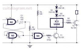
Here the circuit diagram of musical bell with touch switch and timer. This circuit is designed around CMOS IC CD4011 which work as the delay timer and IC UM66 which is well-known musical sound generator. When touch plates are bridged (touched) by hand for a moment, the circuit will start to produce music sound. Just after a short period (few seconds), the musical sound from this circuit will automatically stop.
(View)
View full Circuit Diagram | Comments | Reading(916)
Notebook Anti Theft Protector
Published:2013/3/25 3:43:00 Author:Ecco | Keyword: Notebook, Anti Theft Protector
Here the notebook anti theft protector circuit to secure your important netbook / notebook from stealing. Basically, this is a mini security alarm generator. Fixed inside the notebook case, it will definitely sound a noisy alarm when a person attempts to grab the notebook. This very sensitive circuit utilizes a homemade tilt switch to turn on the alarm system through tilting of the laptop computer case.
(View)
View full Circuit Diagram | Comments | Reading(1018)
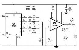
Meter/ Data Acquisition Amplifier
Published:2013/3/25 3:35:00 Author:Ecco | Keyword: Meter, Data, Acquisition Amplifier

The LM385-2.5 injects current into the summing node through an adjustable resistor with a value near 1 megohm. A good-quality fixed resistor near 900k and a 200k potentiometer would be a good combination. The zero pot is adjusted to get an output near -10 volts with the input grounded (assuming -10 volts is the negative limit of the data acquisition device - other offsets are possible). The gain will be near 5 with no gain set resistor, and will reach about 100 with a 41k resistor. The zero might vary slightly when the gain is changed. Use a good-quality 3.9 megohm resistor. Lower values may be used for all the gain-setting resistors.
(View)
View full Circuit Diagram | Comments | Reading(981)
Class-A Audio Amplifiers
Published:2013/3/25 3:25:00 Author:Ecco | Keyword: Class-A Audio Amplifier
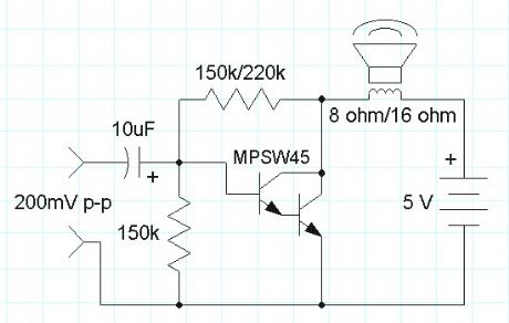
A class-A audio amplifier is pretty wasteful of power but when plenty of power is available the simplicity is attractive. Here is a simple darlington transistor example intended for use with a 5 volt power supply:
(View)
View full Circuit Diagram | Comments | Reading(1086)
Crystal Radio (and other purpose) Audio Amplifier
Published:2013/3/25 3:25:00 Author:Ecco | Keyword: Crystal Radio , Audio Amplifier
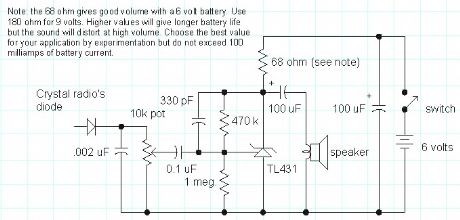
Here is a simple audio amplifier using a TL431 shunt regulator. The amplifier will provide room-filling volume from an ordinary crystal radio outfitted with a long-wire antenna and good ground. The circuitry is similar in complexity to a simple one-transistor radio but the performance is superior (with the exception of the amazing one-transistor reflex ). The TL431 is available in a TO-92 package and it looks like an ordinary transistor so your hobbyist friends will be impressed by the volume you are getting with only one transistor and the amplifier may be used for other projects, too. Higher impedance headphones and speakers may also be used. An earphone from an old telephone will give ear-splitting volume and great sensitivity! The 68 ohm resistor may be increased to several hundred ohms when using high impedance earphones to save battery power.
(View)
View full Circuit Diagram | Comments | Reading(1514)
Op-Amp Audio Amplifier
Published:2013/3/25 3:24:00 Author:Ecco | Keyword: Op-Amp Audio Amplifier

The above circuit is a versatile audio amplifier employing a low cost LM358 op-amp. The differential inputs give the amplifier excellent immunity to common-mode signals which are a common cause of amplifier instability. The dotted ground connection represents the wiring in a typical project illustrating how the ground sensing input can be connected to the ground at the source of the audio instead of at the amplifier where high currents are present. If the source is a power supply referenced signal then one of the amplifier inputs is connected to the positive supply. For example, an NPN common-emitter preamplifier may be added for very high gain and by connecting the differential inputs across the collector resistor instead of from collector to ground, destabilizing feedback via the power supply is greatly reduced.
(View)
View full Circuit Diagram | Comments | Reading(1800)
Computer Audio Booster
Published:2013/3/25 3:23:00 Author:Ecco | Keyword: Computer Audio Booster
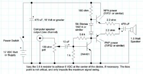
Here is a simple amplifier for boosting the audio level from low-power sound cards or other audio sources driving small speakers like toys or small transistor radios. The circuit will deliver about 2 watts as shown. The parts are not critical and substitutions will usually work. The two 2.2 ohm resistors may be replaced with one 3.9 ohm resistor in either emitter.
(View)
View full Circuit Diagram | Comments | Reading(1614)
| Pages:137/2234 At 20121122123124125126127128129130131132133134135136137138139140Under 20 |
Circuit Categories
power supply circuit
Amplifier Circuit
Basic Circuit
LED and Light Circuit
Sensor Circuit
Signal Processing
Electrical Equipment Circuit
Control Circuit
Remote Control Circuit
A/D-D/A Converter Circuit
Audio Circuit
Measuring and Test Circuit
Communication Circuit
Computer-Related Circuit
555 Circuit
Automotive Circuit
Repairing Circuit